Installation- brake (continued) – Nexen DFE-2500 964009 User Manual
Page 6
6
FORM NO. L-20021-E-0110
QFE
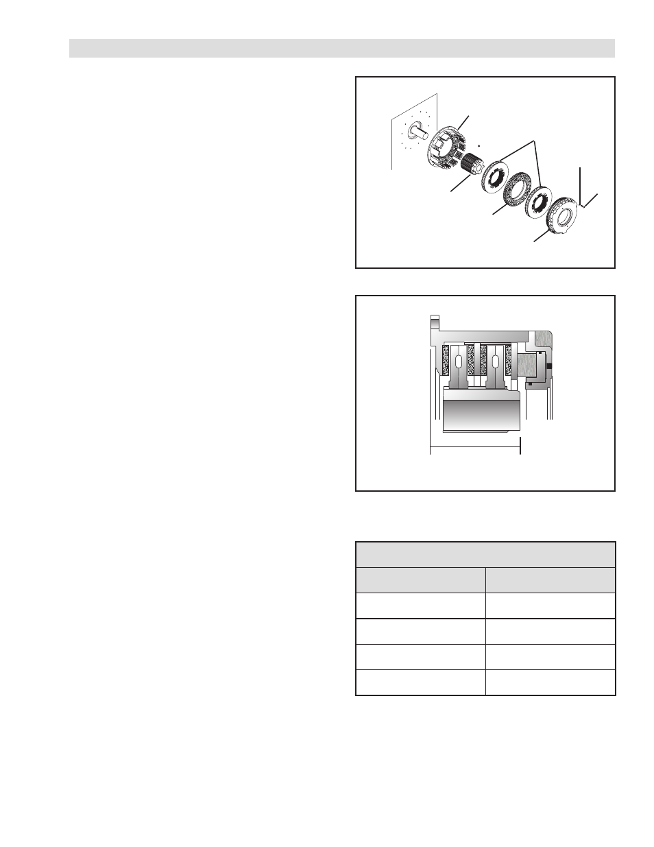
Refer to Figures 3 & 4.
1. Provide a piloting flange and 5/8-11 tapped holes to
a non-rotating surface of the machine.
NOTE: Control perpendicularity between the machine
shaft and the mounting surface of the Housing
(Item 2) as the cap screws are tightened. Use
a dial indicator for measurements and the
machine surfaces of the housing posts as a
reference surface. Perpendicularity should be
less than 0.015'' [0.381 mm].
2. Using customer supplied cap screws, secure the
Housing (Item 2) to the non-rotating part of the machine.
3. Tighten the customer supplied cap screws to 233 Ft.
Lbs. [315.90 Nm] torque.
4. Install a customer supplied key into the shaft; then,
slide the Hub (Item 1) onto the shaft.
NOTE: The axial location of the Hub (Item 1) is critical
to the proper operation of the QFE—BRAKE.
Refer to Table 2 and Figure 4 for correct Hub
location.
5. Using a customer supplied set screw, secure the Hub
(Item 1) to the machine shaft.
6. Coat the teeth of the Hub (Item 1) with Never-Seez
®
.
7. Slide the first Disc Assembly (Item 4) onto the Hub
(Item 1).
8. Slide the Facing Plate (Item 24) onto the Hub (Item 1).
9. Slide the second Disc Assembly (Item 4) onto the Hub
(Item 1).
NOTE: On QFE 1650 and QFE 2200 the Piston and
Pressure Plate are one item.
10. Assemble the Cylinder (Item 5), Piston (Item 6), and
Pressure Plate (Item 7) to the Housing (Item 2).
11. Using the Cap Screws (Item 14) and Lockwashers
(Item 20), secure the Cylinder (Item 5) to the Housing
(Item 2).
12. Alternately and evenly tighten the Cap Screws (Item
14) to 119 ft. lbs. [161.34 Nm] torque.
FIGURE 3
2
1
24
4
5/6/7
20
14
TABLE 2
Q
]
N
O
I
T
A
C
O
L
B
U
H
E
F
Q
L
E
D
O
M
N
O
I
T
A
C
O
L
B
U
H
0
5
1
1
-
E
F
Q
]
m
m
7
3
2
.
2
7
1
[
"
1
8
7
.
6
0
5
6
1
-
E
F
Q
]
m
m
6
9
5
.
6
9
1
[
"
0
4
7
.
7
0
0
2
2
-
E
F
Q
]
m
m
9
9
9
.
6
6
2
[
"
7
3
9
.
8
0
0
5
2
-
E
F
m
m
7
8
7
.
7
7
2
[
"
8
6
9
.
8
FIGURE 4
Hub Location
INSTALLATION- BRAKE (continued)
- QFE-1650 964064 QFE-1650 964046 DFE-1150 964000 DFE-1150 964178 DFE-1150 964043 DFE-1150 964255 DFE-1150 964179 QFE-2200 964066 DFE-2500 964010 DFE-2500 964049 DFE-1150 964001 DFE-1150 964002 DFE-1150 964005 QFE-2200 964067 QFE-2200 964058 QFE-2500 964069 QFE-1150 964060 QFE-1150 964093 QFE-2500 964070 QFE-2500 964047 QFE-1150 964061 QFE-1150 964041 QFE-1150 964062 DFE-1650 964003 DFE-1650 964050 DFE-1650 964203 DFE-1650 964057 DFE-1650 964042 DFE-1650 964048 DFE-1650 964304 DFE-1650 964004 DFE-1650 964024 DFE-1650 964056 DFE-1650 964044 DFE-1650 964027 DFE-2200 964006 QFE-1650 964063 DFE-2200 964007 DFE-1150 964016 DFE-1650 964019 DFE-2200 964022 DFE-2500 964025 QFE-1150 964088 QFE-1650 964091 QFE-2200 964094 QFE-2500 964097