Lubrication – Nexen DB 835071 User Manual
Page 6
6
FORM NO. L-20011-J-0711
NOTE
Nexen pneumatically actuated devices require clean, pressure regulated air for maximum performance and
life. All seals in Nexen pneumatically operated devices are lubricated for life, and do not require additional
lubrication.
However, some customers prefer to use an air line lubricator, which injects oil into the pressurized air, forcing
an oil mist into the air chamber. This is acceptable, but care must be taken to ensure once an air mist lubrication
system is used, it is continually used over the life of the product as the oil mist may wash free the factory
installed lubrication.
Locate the lubricator above and within ten feet of the product, and use low viscosity oil such as SAE-10.
Synthetic lubricants are not recommended.
Nexen product's bearings are shielded and pre-lubricated, and require no further lubrication.
LUBRICATOR DRIP RATE SETTINGS
1. Close and disconnect the air line from the unit.
2. Turn the Lubricator Adjustment Knob counterclockwise three
complete turns.
3. Open the air line.
LUBRICATION
CAUTION
These settings are for Nexen supplied
lubricators. If you are not using a Nexen
lubricator, calibration must follow the
manufacturer's suggested procedure.
4. Close the air line to the unit when a drop of oil forms in the
Lubricator Sight Gage.
5. Connect the air line to th e unit.
6. Turn the Lubricator Adjustment Knob clockwise until
closed.
7. Turn the Lubricator Adjustment Knob counterclockwise one-
third turn.
8. Open the air line to the unit.
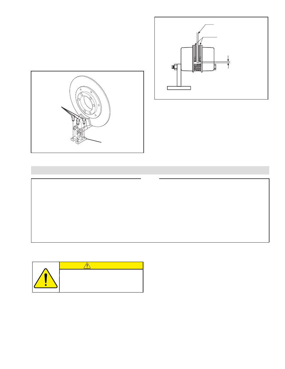
7. Mount the Caliper Brake so the radius of the Disc
runs approximately 0.0625 In. [1.587 mm] below the
outside radius of the Shoe Assembly (Item 1), and
with an equal distance between the Disc and the
Shoe Assemblies (See Figure 3).
8. Use customer supplied 3/8 In. bolts to mount the
''T'' Support (Item 12) to a solid base (See Figures
3 and 4).
FIGURE 3
Brake Disc centered
between the Shoe
Assemblies
Shoe Assemblies
0.0625 In.
[1.587 mm]
FIGURE 4
Customer Supplied
3/8 In. Bolts
"T" Support
(Item 12)