Nexen DB 835071 User Manual
Page 7
7
FORM NO. L-20011-J-0711
AIR CONNECTIONS
NOTE
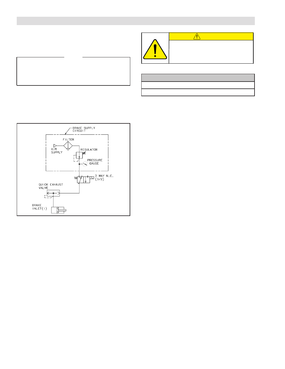
For quick response, Nexen recommends a quick exhaust
valve and short air lines between the Control Valves and
the product. Align the air inlet ports to a down position
to allow condensation to drain out of the air chambers
of the product.
CAUTION
Low air pressure will cause slippage and
overheating. Excessive air pressure will
cause abrupt starts and stops, reducing
product life.
All Nexen pneumatically actuated devices require clean
and dry air, which meet or exceeds ISO 8573.1:2001
Class 4.4.3 quality.
Air Pressure (Gage) Limits
6.9 Bar (100 PSI) Absolute Max.
0 Bar (0 PSI) Absolute Min.
The following is a common air supply scheme used with
this product. This is an example and not an all-inclusive
list. All air circuits to be used with this product must be
designed following EN983 guidelines.
OPTIONAL DB AIR HOSE ASSEMBLY, #835400
Hose Assembly Description:
Hose: 8-inches with swivel nuts on each end. One end
has a tee connector and the other end has an elbow
connector.
Assembly Instructions:
Wrap the 1/8-NPT threads on the elbow and tee with
Teflon sealing tape and install into the brake air inlet ports.
Connection with air supply to the open end of the tee.