Installation, Caution – Nexen DBSE 835030 User Manual
Page 5
5
FORM NO. L-20017-C-1212
INSTALLATION
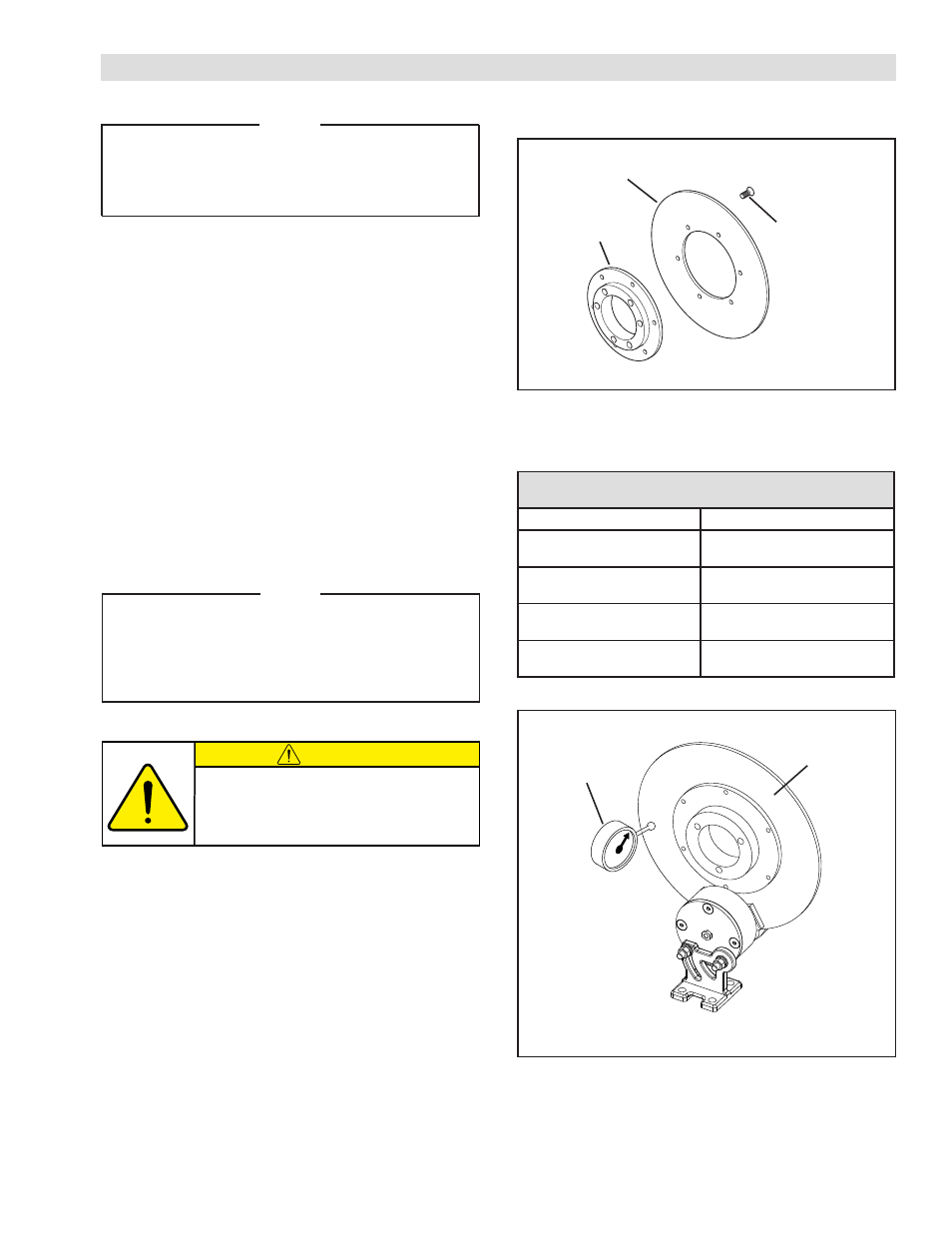
NOTE
The Brake Disc (ordered separately) may be
mounted to a customer supplied hub or mounted
to the Nexen Disc Brake Hub (also ordered
separately) for use with a Q.D. Bushing.
Refer to Figure 1-2 & Table 1.
1. Apply a drop of Loctite
®
242 to the threads of the six
Flat Head Hex Socket Cap Screws provided with the
Brake Disc and secure the Brake Disc to the Brake
Disc Hub or to a customer-supplied hub.
2. Alternately and evenly tighten the six Flat Head Hex
Socket Cap Screws to the recommended torque.
3. Thoroughly inspect the tapered bore of the Brake Disc
Hub and the tapered surface of the Q. D. Bushing.
Remove any dirt, grease, or foreign material. Do not
use lubricants for this installation.
4. Assemble the Q.D. Busing into the Brake Disc Hub,
aligning the untapped holes in the Q.D. bushing with
the tapped holes in the Brake Disc Hub.
NOTE
Runout is minimized if a Dial Indicator is used as
the pull-up bolts are tightened. Place the contact
tip of the Dial Indicator on the machined surface of
the Brake Disc to measure runout. Runout should
be less than 0.010-0.015 in. [.254-.381 mm.].
Brake Disc
Brake Disc
Hub
Flat Head Hex
Socket Cap
Screw
FIGURE 1
RECOMMENDED TIGHTENING TORQUES
FLAT HEAD HEX SOCKET CAP SCREWS
MODEL
TORQUE
10 in. Disc
(Prod. No. 855500)
45 in-lb (5.04 Nm)
12 in. Disc
(Prod. No. 855600)
105 in-lb (11.76 Nm)
14 in. Disc
(Prod. No. 855700)
105 in-lb (11.76 Nm)
16 in. Disc
(Prod. No. 855800)
105 in-lb (11.76 Nm)
Dial Indicator
Brake Disc
FIGURE 2
TABLE 1
CAUTION
If excessive tightening torque is applied, bursting
pressures are created in the Brake Hub. There must
be a gap between the flange of the Q. D. Bushing
and the Brake Disc to ensure a proper fit of the Q. D.
Bushing onto the shaft.