Installation – Nexen J 841600 User Manual
Page 5
5
FORM NO. L-20012-L-1209
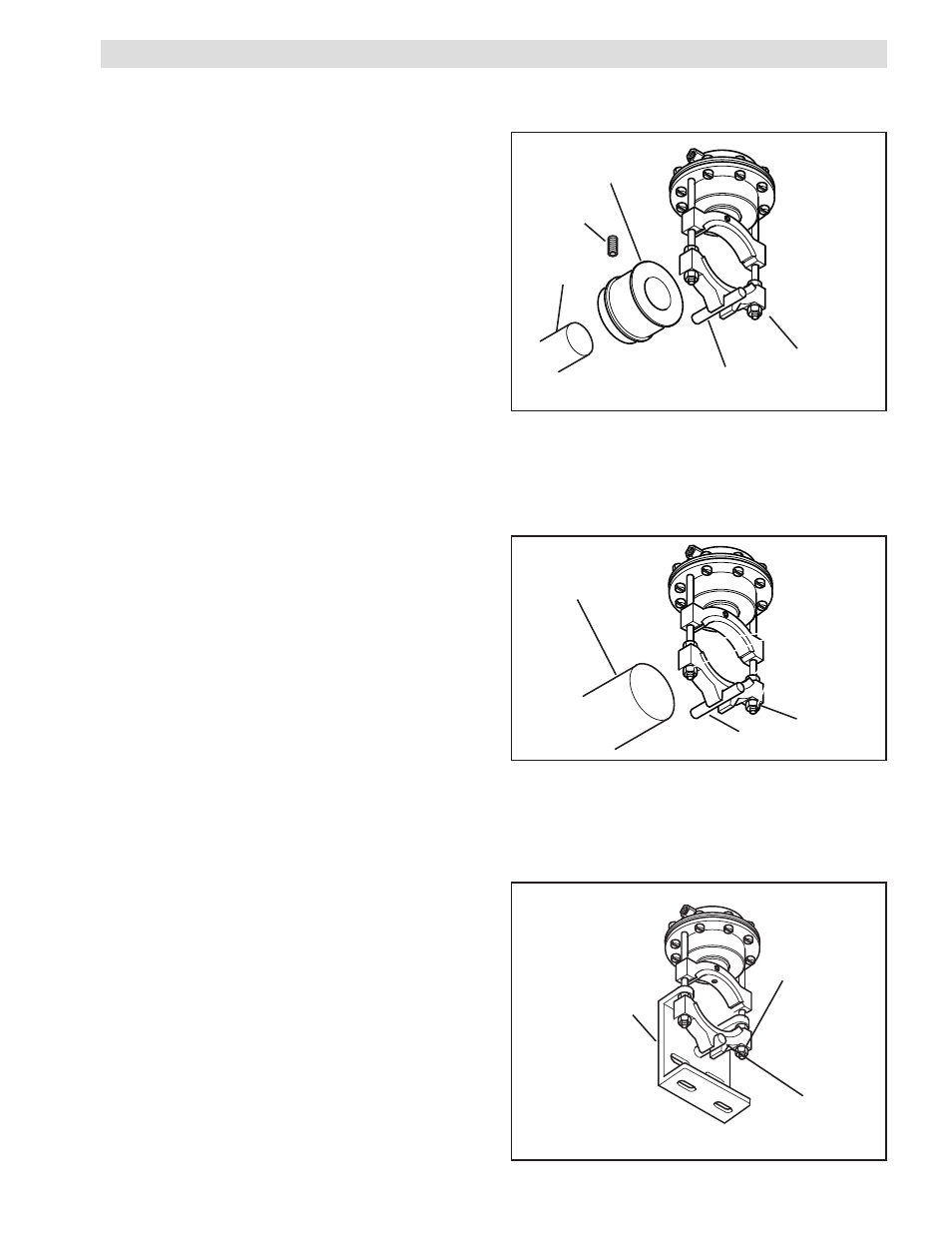
Pin
Hex. Head
Jam Nut
Self-Centering
Bracket
FIGURE 3
INSTALLATION
''J'' OR ''K'' DIAPHRAGM BRAKE WITH OPTIONAL DRUM
NOTE: Refer to Figure 1.
1. Slide the Optional Drum onto the shaft.
2. Tighten the Set Screw; securing the Optional Drum to the
shaft.
3. Position the ''J'' or ''K'' Diaphragm Brake on the Optional
Drum, with the Pin passing through the slot in the Fixed
Shoe.
4. Adjust the Fixed Shoe by loosening the Hex. Head Jam Nuts
to provide sufficient clearance between the Facings and
Optional Drum to allow free rotation of the Optional Drum;
then, tighten the Hex. Head Jam Nuts.
''J'' OR ''K'' DIAPHRAGM BRAKE WITHOUT OPTIONAL DRUM
NOTE: Refer to Figure 2.
1. Position the ''J'' or ''K'' Diaphragm Brake on the shaft, with
the Pin passing through the slot in the Fixed Shoe.
2. Adjust the Fixed Shoe by loosening the Hex. Head Jam
Nuts to provide sufficient clearance between the Facings
and shaft to allow free rotation of the shaft; then, tighten the
Hex. Head Jam Nuts.
OPTIONAL SELF-CENTERING BRACKET
NOTE: Refer to Figure 3.
1. Position the ''J'' or ''K'' Diaphragm Brake with the diaphragm
facing up on the shaft or Optional Drum with the Pin passing
through the slot in the Fixed Shoe.
2. Secure the Optional Self-Centering Bracket to the machine
or support.
3. Adjust the Fixed Shoe by loosening the Hex. Head Jam Nuts
to provide sufficient clearance between the Facings and
shaft or Optional Drum to allow free rotation of the shaft or
Optional Drum; then, tighten the Hex. Head Jam Nuts.
Shaft
Set
Screw
Optional
Drum
Pin
FIGURE 1
Hex Head
Jam Nut
FIGURE 2
Pin
Shaft
Hex Head
Jam Nut