Nexen FMCB-7-38 801613 User Manual
Page 10
10
FORM NO. L-20179-H-1209
FrICTIOn FaCInGS continued
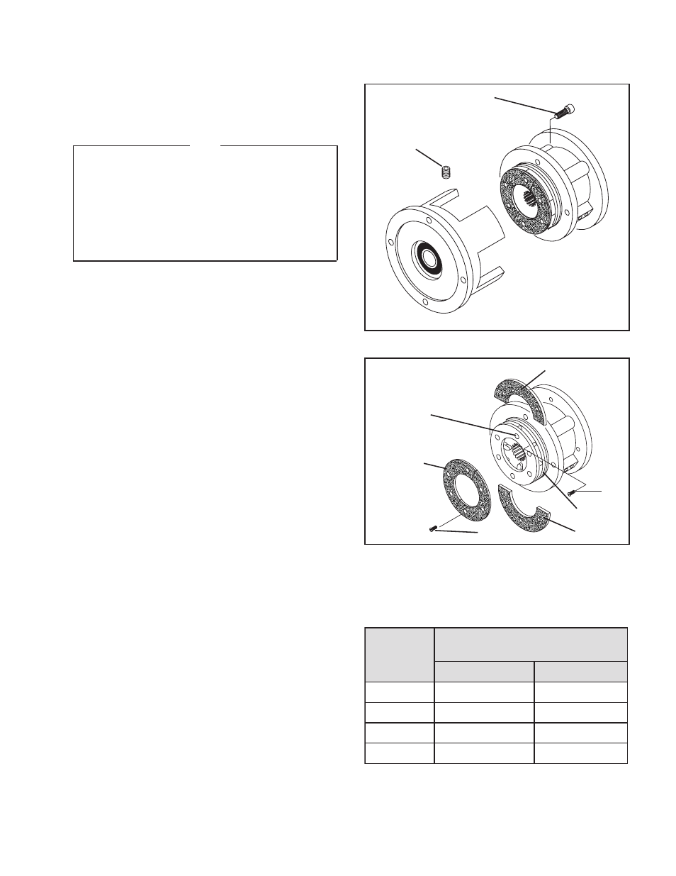
FMCB 7-28, 7-38, 8-38, anD 8-42
refer to Figures 6 & 7.
note
If an Input unit is installed on the FMCB, it must be
removed before servicing the FMCB. loosen the
Set Screw (Item 35) to release the FMCB from the
Input unit shaft.
On Models 7-28 and 7-38, the Socket Head Cap
Screws are Item 8. On Models 8-38 and 8-42, the
Socket Head Cap Screws are Item 15.
1. Remove the four Socket Head Cap Screws and
separate the two halves of the FMCB.
2. Remove the six old Flat Head Screws (Item 12) and
the first old Friction Facing (Item 11).
3. Align the holes in the Splined Disc (Item 9) with the
Flat Head Screws (Item 12) that secure the second
split Friction Facing (Item 13).
4. Remove the six old Flat Head Screws (Item 12) and
the second old Friction Facing (Item 13).
5. Install the first new split Friction Facing (Item 13) and
new Flat Head Screws (Item 12).
6. Tighten the six new Flat Head Screws (Item 12) to
8.02 Nm [71 in-lb] torque.
7. Install the second new Friction Facing (Item 11), new
Flat Head Screws (Item 12), and Backing Plate (Item
10).
8. Tighten the six new Flat Head Screws (Item 12) to
8.02 Nm [71 in-lb] torque.
9. Apply a drop of Loctite
®
242 to the threads of the
Socket Head Cap Screws (Item 8 or 15).
10. Install and tighten the four Socket Head Cap
Screws securing the two halves of the FMCB to the
recommended torque (See Table 1).
Figure 6
Socket Head Cap Screw
(Item 8 or 15)
Set Screw (Item 35)
Figure 7
12
13
13
11
12
Insert screwdriver to
remove second split
Friction Facing.
9
B
C
M
F
l
e
d
o
M
w
e
r
c
S
p
a
C
d
a
e
H
t
e
k
c
o
S
e
u
q
r
o
T
g
n
i
n
e
t
h
g
i
T
d
e
d
n
e
m
m
o
c
e
R
8
m
e
tI
5
1
m
e
tI
8
2
-
7
]
b
l-
tf
5
.
4
2
[
m
N
2
.
3
3
--
-
8
3
-
7
]
b
l-
tf
5
.
4
2
[
m
N
2
.
3
3
--
-
8
3
-
8
--
-
]
b
l-
tf
5
.
9
4
[
m
N
1
.
7
6
2
4
-
8
--
-
]
b
l-
tf
5
.
9
4
[
m
N
1
.
7
6
Table 1
- FMCB-8-42 801619 FMCB-8-38 801616 FMCB-130-19 801400 FMCB-130-24 801403 FMCB-7-28 801610 FM 7-28 Input Unit 801627 FM 7-28 Input Unit 801575 FM 8-38 Input Unit 801629 FM 8-38 Input Unit 801601 FM 7-38 Input Unit 801628 FM 7-38 Input Unit 801608 FM 8-42 Input Unit 801630 FM 8-42 Input Unit 801602 FMCBE-875 801428 FMCBE-7-38 801638 FMCBE-7-28 801637 FMCBE-8-38 801639 FMCBE-8-42 801640