Nexen MWB 847501 User Manual
Page 5
2
FORM NO. L-20010-G-1209
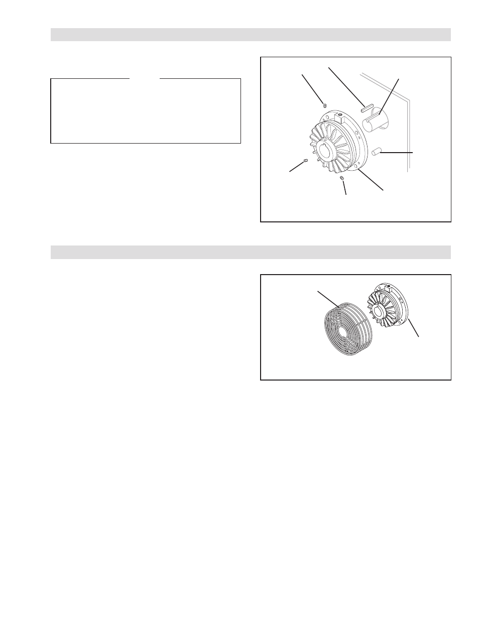
FIGURE 1
REFER TO FIGURE 1.
NOTE
The brake may be secured to the machine
surface by using either the four holes in the
Air Chamber (Item 8) and bolting the brake
to the machine housing or by using a torque
pin through the slot in the bottom of the Air
Chamber.
1. Insert the Key (Item 16) into the machine shaft and
slide the brake over the machine shaft and Key.
2. Install and tighten the three Set Screws (Item 1) to
secure the brake to the machine shaft.
INSTALLATION
1
1
1
Air
Chamber
(Item 8)
16
Machine Shaft
Torque
Pin
FIGURE 2
BRAKE GUARD INSTALLATION
REFER TO FIGURE 2.
1. Align the mounting holes of the Brake Guard with
the four tapped holes in the Air Chamber or the
brake.
2. Using four Phillips Head Pan Screws, secure the
Brake Guard to brake. Tighten to 35 in-lbs [4 Nm].
BRAKE GUARD INSTALLATION
Brake Guard
Air
Chamber