Nexen MWB 847501 User Manual
Page 8
5
FORM NO. L-20010-G-1209
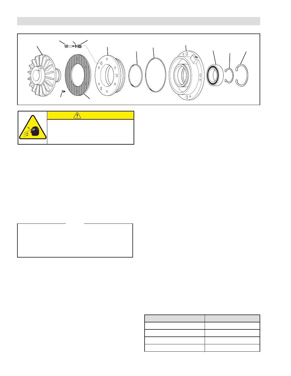
REFER TO FIGURE 3.
1. Remove the Retaining Ring (Item 13) and press the
Hub Assembly (Item 2) out of the Ball Bearing (Item
14) and Air Chamber (Item 8).
2. Remove the Retaining Ring (Item 12) from the Air
Chamber (Item 8); then, press the old Ball Bearing
(Item 14) out of the Air Chamber.
3. Remove the six old Flat Head Machine Screws (Item
3) securing the old Friction Facing (Item 4) to the
Piston (Item 5); then, remove the Friction Facing.
NOTE
The, LWB, MWB, and HWB have six Shoulder
Bolts (Item 6), Compression Springs (Item 7),
and O-ring Seals (Item 10). The FWB has three
Shoulder Bolts (Item 6), Compression Springs
(Item 7), and O-ring Seals (Item 10).
4. Remove the old Shoulder Bolts (Item 6), O-ring
Seals (Item 10), and Compression Springs (Item 7)
from the Piston (Item 5).
5. Slide the Piston (Item 5) out of the Air Chamber
(Item 8) and remove the O-ring Seals (Item 9 and
11) from the Piston and Air Chamber.
6. Clean the bearing bore of the Air Chamber (Item
8) with fresh solvent, making sure all old Loctite
®
residue is removed.
7. Apply an adequate amount of Loctite
®
680 to evenly
coat the outer race of the new Ball Bearing (Item 14)
and press the new Ball Bearing into the Air Chamber
(Item 8).
PARTS REPLACEMENT
FIGURE 3
CAUTION
Working with spring loaded or tension
loaded fasteners and devices can cause
injury. Wear safety glasses and take the
appropriate safety precautions.
8. Reinstall the Retaining Ring (Item 12).
9. Apply a thin film of o-ring lubricant to the new O-ring
Seals (Items 9, 10, and 11) and the o-ring contact
surfaces of the Piston (Item 5), Air Chamber (Item 8),
and new Shoulder Bolts (Item 6).
10. Install the new O-ring Seals (Items 9, 10, and 11).
11. Slide the Piston into the Air Chamber, aligning the
holes in the Piston with the holes in the Air Chamber.
12. Slide a new Compression Spring (Item 7) onto each
new Shoulder Bolt (Item 6).
13. Install the new Shoulder Bolts (Item 6), Compression
Springs (Item 7), and O-ring Seals (Item 10) through
the Piston (Item 5) and into the Air Chamber (Item 8).
14. Alternately and evenly tighten the new Shoulder
Bolts (Item 6) to the torque specified in Table 2.
15. Using six new Flat Head Machine Screws (Item 3),
secure the new Friction Facing (Item 4) to the Piston
(Item 5).
16. Tighten the six Flat Head Machine Screws (Item 3) to
22 in-lbs [2.50 Nm] torque.
17. While supporting the inner race of the new Ball
Bearing (Item 14), press the Hub Assembly (Item 2)
into the new Ball Bearing and Air Chamber (Item 8).
18. Reinstall the Retaining Ring (Item 13).
8
14
9
11
7
10
6
2
4
3
5
12
13
Model
Torque
FWB
43 in-lbs [4.8 Nm]
LWB
43 in-lbs [4.8 Nm]
MWB
205 in-lbs [23.1 Nm]
HWB
345 in-lbs [40 Nm]
TABLE 2 SHOULDER BOLT TIGHTENING TORQUE