Warning – Nexen FMCE 625 801683 User Manual
Page 5
FORM NO. L-20321-C-0402
2
FIGURE 4
23
19
18
19
24
20
(Item 18)
For models
875 and 1125
only.
FIGURE 5
23
19
18
19
24
Press this Ball Bearing
onto the Stub Shaft
(Item 23) first (See
Step 7).
20
(Item 18)
For models
875 and 1125
only.
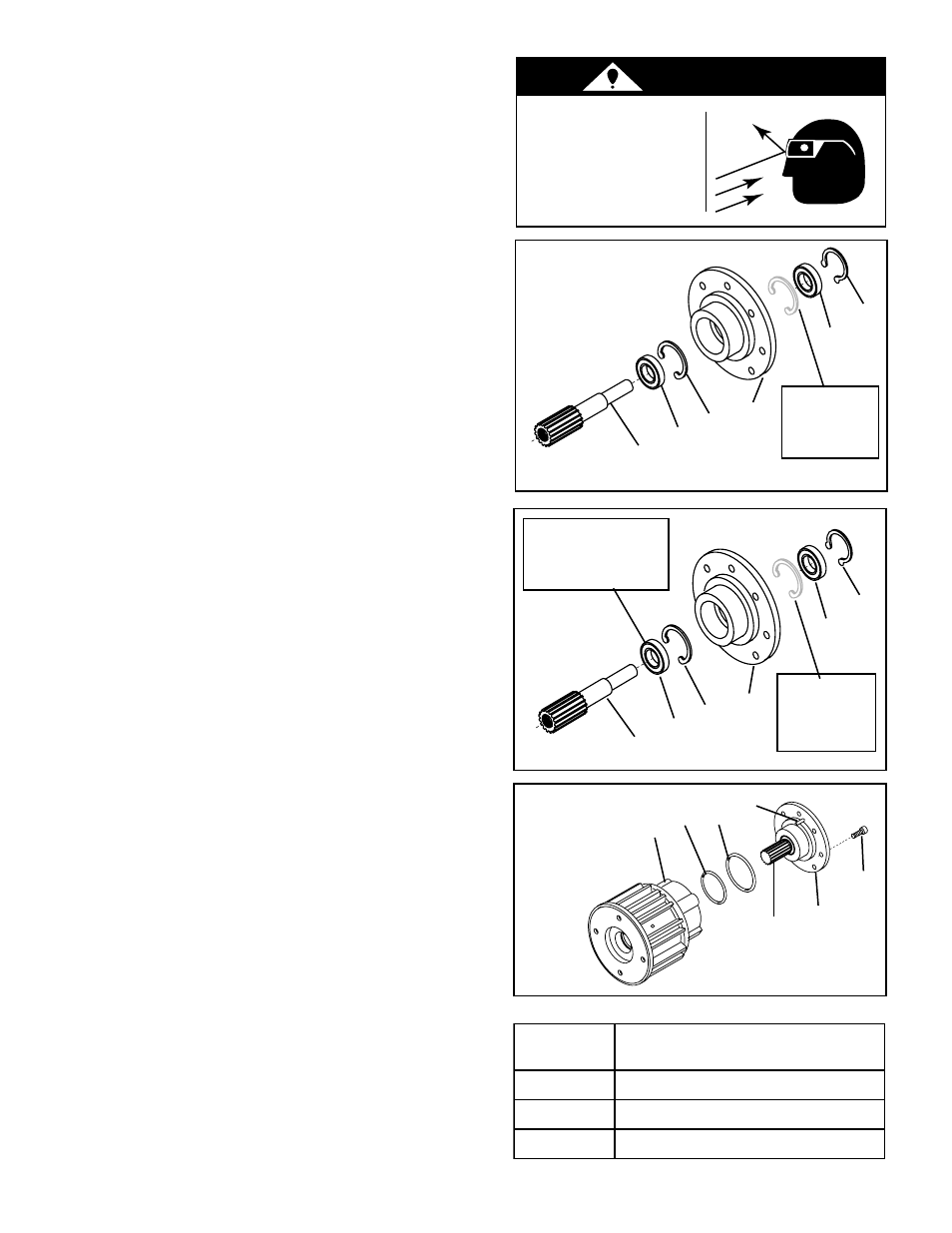
3.
Remove the Retaining Ring (Item 24) and press the
Stub Shaft (Item 23) out of the Male Pilot (Item 20)
(See Figure 4).
NOTE: The two old Ball Bearings (Item 19) are
removed from opposite ends of the Male Pilot
(Item 20). Do not remove the Retaining Ring(s)
(Item 18) (See Figure 4).
5.
Remove the two old Ball Bearings (Item 19) from
the Male Pilot (Item 20) (See Figure 4).
6.
Clean the bearing bore of the Male Pilot (Item 20)
with fresh safety solvent, making sure all old
Loctite
®
residue is removed (See Figure 4).
7.
Press one new Ball Bearing (Item 19) onto the new
Stub Shaft (Item 23) (See Figure 5).
8.
Apply an adequate amount of Loctite
®
680 to
evenly coat the outer race of the second new Ball
Bearing (Item 19) and press it into the output side
of the Male Pilot (Item 20) until it is seated against
the Retaining Ring (Item 18) inside the Male Pilot
(See Figure 5).
NOTE: Model 625 FMCBE does not have a
Second Retaining Ring (Item 18).
9.
Apply an adequate amount of Loctite
®
680 to evenly
coat the outer race of the new Ball Bearing (Item 19)
pressed onto the Stub Shaft (Item 23). Then, press
the new Ball Bearing and Stub Shaft into the Male
Pilot (Item 20) until the Ball Bearing is seated
against the Retaining Ring (Item 18) (See Figure 5).
10. Lubricate the new O-rings Seals (Items 21 and 22)
and the contact surfaces on the Male Pilot (Item
20) and Air Chamber (Item 12) with a thin film of
fresh o-ring lubricant.
11. Install the new O-ring Seals (Items 21 and 22)
(See Figure 6).
12. Lubricate the splines of the new Stub Shaft (Item
23) with a thin film of Never-Seez
®
.
13. Align the Spring Pin (Item 17) on the Male Pilot
(Item 20) with the hole in the Piston (Item 16) and
slide the Male Pilot into the Piston and Housing
(Item 1) (See Figure 6).
14. Apply a drop of Loctite
®
242 to the threads of four
Socket Head Cap Screws (Item 13) and secure the
Male Pilot (Item 20) to the Air Chamber (Item 12)
(See Figure 6).
15. Tighten the four Socket Head Cap Screws to the
recommended torque (See Table 1).
NOTE: See L-20319 for pertinent information
regarding installation, operation, and
maintenance of the FMCBE Locking Key unit.
FIGURE 6
12
22
21
20
13
23
17
TABLE 1
E
B
C
M
F
L
E
D
O
M
E
U
Q
R
O
T
G
N
I
N
E
T
H
G
I
T
D
E
D
N
E
M
M
O
C
E
R
)
3
1
M
E
T
I
(
5
2
6
]
m
N
7
1
.
4
[
b
l
-
t
f
5
.
0
1
5
7
8
]
m
N
6
0
.
3
3
[
b
l
-
t
f
5
.
4
2
5
2
1
1
]
m
N
6
0
.
3
3
[
b
l
-
t
f
5
.
4
2
WARNING
Always wear safety
goggles when
working with spring
or tension loaded
devices such as
retaining rings.