Sensor roll, Web forces, Sizing sensors tare forces – Nexen MB25B 911996 User Manual
Page 7: Minimum web angle is 0, Tare per sensor
FORM NO. L-20127-L-0513
7
The Sensor Roll, which transfers the force generated by
web tension to the MB Tension Sensors, may be made of
any material compatible with the materials being handled
and the system requirements. Dimensional considerations
for designing the Sensor Roll are length and diameter. The
length of the roll should be short enough to allow for some
lateral adjustment when installing the roll between the
bearings. The diameter must be designed to accommodate
web speed and bearing life.
Weight may also be a design factor, particularly when
dealing with very low web tensions. In low tension systems,
a heavy roll may cause false tension readings. Bearings
selected for low tension systems should have low frictional
resistance for the same reason.
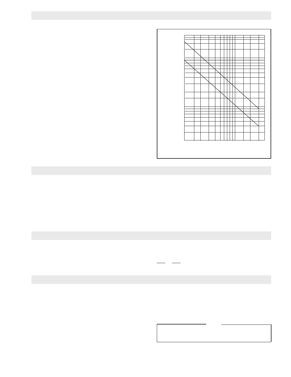
Unbalance in the Sensor Roll is picked up by the MB
Tension Sensors, causing false readings. Dynamically
balance the Sensor Roll to tolerance as shown (See Figure
10). The upper line indicates minimum acceptable balance
specification. The lower line indicates practical balance
limits (balance to closer tolerances is not cost effective).
Web angle is the angle between the plane of the web as
it approaches the Sensor Roll and the plane of the web as
it leaves X + Y or X’ +Y’ (See Figure 11), A + B or A’ + B’
(See Figure 12). Maximum web angle is 150
o
; minimum
web angle is 0
o
.
All MB Tension Sensors may be mounted with the web angle
in the Normal Wrap direction; i.e., the resultant force F is
toward the MB Tension Sensors (See Figures 11 and 12).
MB Tension Sensors MB05, MB11, and MB25 may also
be mounted with Reverse Wrap; i.e., the resultant force F’
away from the MB Tension Sensor (See Figures 11 and
12). Web may travel in either direction.
NOTE
Due to the high forces generated by webs needing
MB Tension Sensors MB33 and MB41, Reverse
Wrap is not recommended.
SENSOR ROLL
FIGURE 10
1
0
0
2
0
0
3
0
0
1
0
0
0
2
0
0
0
3
0
0
0
4
0
0
0
RPM
.500
.400
.200
.150
.100
.050
.040
.030
.020
.015
.010
.005
.004
.003
.002
Unbalance
Tolerance in Oz. In.
per Lb. of Rotating Mass
WEB FORCES
(continued...)
MB Tension Sensors are sized in reference to two forces.
The force exerted on the sensor by the web, calculated as
F or F’ (See Page 8). This force is divided by the number
of support points (which is normally two) for the Sensor
Roll. In cases of narrow web or wire being detected by a
pulley or narrow roll entirely supported by one MB Tension
Sensor, there is only one support.
The other force to be considered is the weight of the roll
and bearings. Both of these forces should be compared to
the permissible ranges as stated in the SPECIFICATIONS
section.
The selected sensor must be able to tolerate both the load
(F or F’) and the tare (roll and bearing weight) applied to it.
SIZING SENSORS
TARE FORCES
Weight of Sensing Roll W _________
Weight of Bearing B ________
Total TARE = W_______+2xB_______=_______
TARE
= = _______ TARE per Sensor
2
2