High level block diagram, Clocking and reset structure for ip core, High level block diagram -4 – Altera 100G Interlaken MegaCore Function User Manual
Page 34: Clocking and reset structure for ip core -4
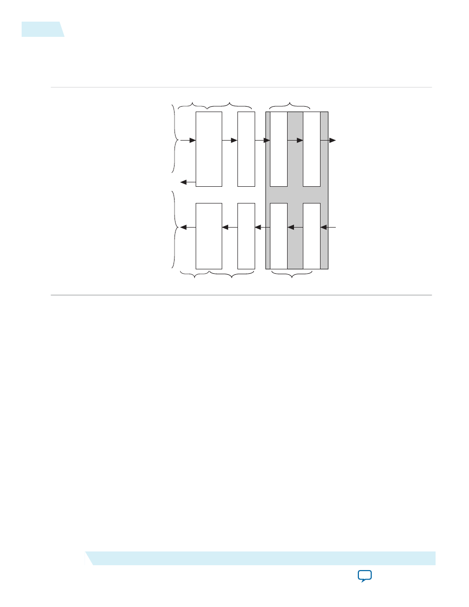
High Level Block Diagram
Figure 4-1: 100G Interlaken Block Diagram
irx_chan[7:0]
irx_num_valid[7:0]
irx_sob[1:0]
irx_eob
irx_sop[1:0]
irx_eopbits[3:0]
irx_dout_words[511:0]
irx_calendar[16 x n - 1:0]
irx_err
itx_chan[7:0]
itx_num_valid[7:0]
itx_sob[1:0]
itx_eob
itx_sop[1:0]
itx_eopbits[3:0]
itx_din_words[511:0]
itx_calendar[16 x n - 1:0]
Transceiver Blocks
TX
PCS
TX
PMA
TX
MAC
TX
Transmit
Buffer
tx_usr_clk
tx_mac_clk
clk_tx_common
clk_rx_common
rx_mac_clk
rx_usr_clk
RX
PCS
RX
PMA
RX
MAC
RX
Regroup
tx_pin[m - 1:0]
rx_pin[m - 1:0]
itx_ready
The 100G Interlaken MegaCore function consists of two paths: an Interlaken TX path and an Interlaken
RX path. Each path includes MAC, PCS, and PMA blocks. The PCS blocks are implemented in hard IP.
Related Information
•
100G Interlaken IP Core Transmit Path Blocks
on page 4-18
For more information about the Interlaken TX path.
•
100G Interlaken IP Core Receive Path Blocks
For more information about the Interlaken RX path.
Clocking and Reset Structure for IP Core
The following topics describe the clocking and reset structure of the 100G Interlaken IP core:
100G Interlaken IP Core Clock Signals
on page 4-5
IP Core Reset Sequence with the Reconfiguration Controller
on page 4-7
4-4
High Level Block Diagram
UG-01128
2015.05.04
Altera Corporation
Functional Description