Circuit board header connection – Altera ByteBlasterMV User Manual
Page 22
2–4
Altera Corporation
Functional Description
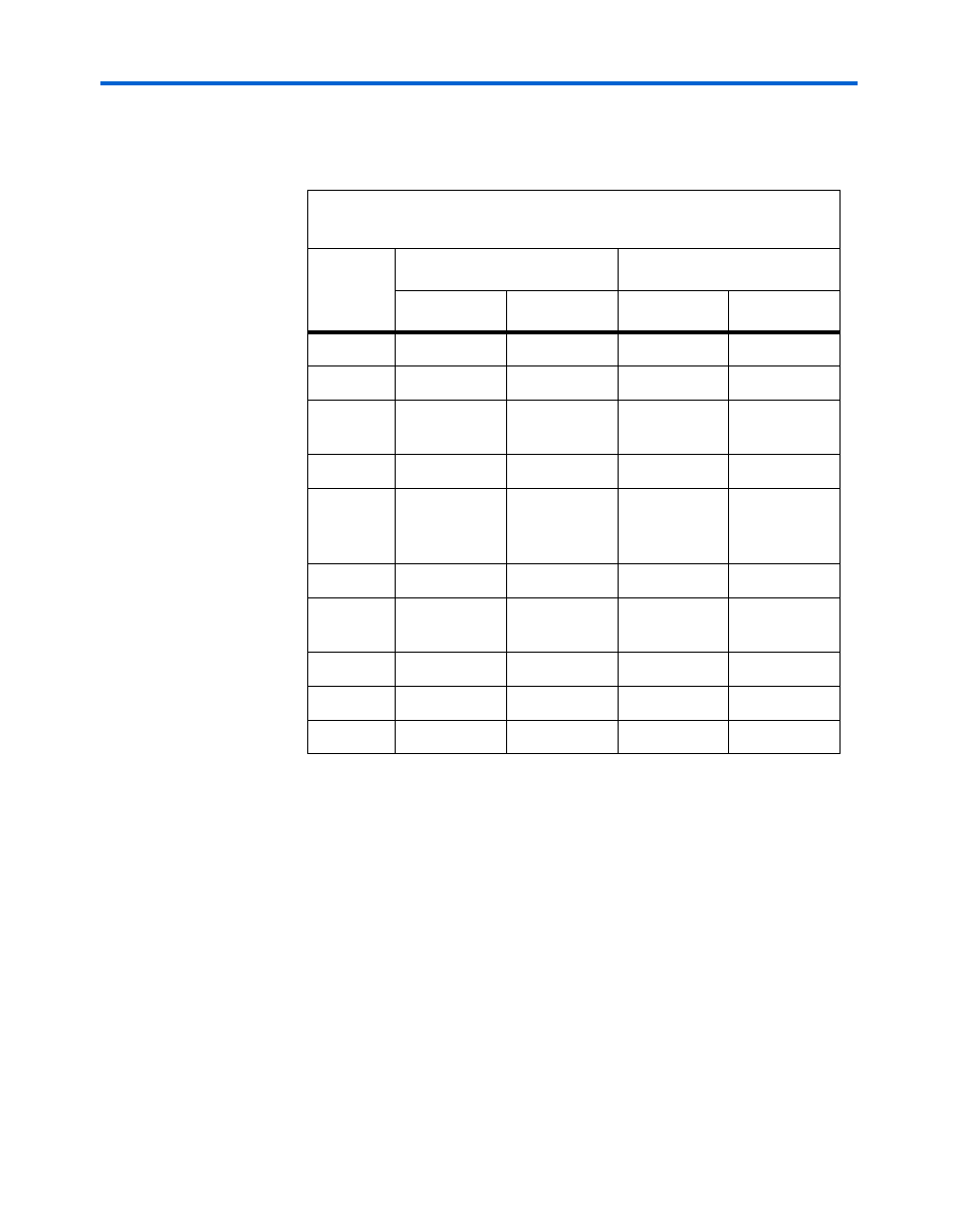
identifies the 10-pin female plug’s pin names for the corresponding
download mode.
1
The circuit board must supply V
CC
and ground to the ByteBlasterMV
cable.
Circuit Board Header Connection
The ByteBlasterMV 10-pin female plug connects to a 10-pin male header on the
circuit board. The 10-pin male header has two rows of five pins, which are
connected to the device’s programming or configuration pins. The
ByteBlasterMV cable receives power and downloads data via the male header.
shows the dimensions of a typical 10-pin male header.
Table 2–3. ByteBlasterMV Female Plug’s Pin Names & Download
Modes
Pin
PS Mode
JTAG Mode
Signal
Description
Signal
Description
1
DCLK
Clock signal
TCK
Clock signal
2
GND
Signal ground
GND
Signal ground
3
CONF_
DONE
Configuration
Done
TDO
Data from
device
4
VCC
Power supply
VCC
Power supply
5
nCONFIG
Configuration
control
TMS
JTAG state
machine
control
6
–
No connect
–
No connect
7
nSTATUS
Configuration
status
–
No connect
8
–
No connect
–
No connect
9
DATA0
Data to device
TDI
Data to device
10
GND
Signal ground
GND
Signal ground