Figure 2–7, Figure 2–8 – Altera RLDRAM II Controller MegaCore Function User Manual
Page 21
Altera Corporation
MegaCore Version 9.1
2–11
November 2009
RLDRAM II Controller MegaCore Function User Guide
Functional Description
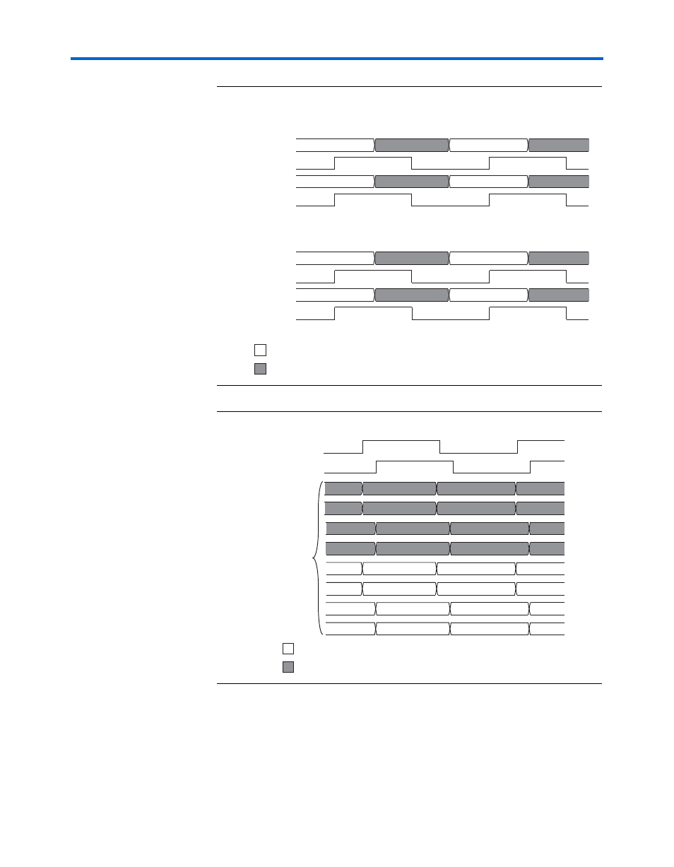
Figure 2–7. Memory Interface
Figure 2–8. Datapath Interface
shows that any read data captured on the rising edge of the
delayed rldramii_qk[] signal is located in the lower half-bit locations
of control_rdata[]. Any read data captured on the falling edge of the
delayed rldramii_qk[] signal is located in the upper half-bit locations
rldramii_dq[35:27]
RLDRAM II
Device 1
RLDRAM II
Device 0
rldramii_qk[3]
rldramii_dq[26:18]
rldramii_qk[2]
rldramii_dq[17:9]
Data associated with rldramii_qk[] rising edge
rldramii_qk[1]
rldramii_dq[8:0]
rldramii_qk[0]
N
P
M
N
O
P
I
J
K
L
E
F
G
H
A
B
C
D
Data associated with rldramii_qk[] falling edge
capture_clk[1]
control_rdata[]
Data associated with rldramii_qk[] rising edge
capture_clk[0]
N
P
J
L
F
H
E
G
I
K
M
O
A
C
B
D
Data associated with rldramii_qk[] falling edge