Altera Stratix II GX PCI Express Development Board User Manual
Page 18
2–8
Reference Manual
Altera Corporation
Stratix II GX PCI Express Development Board
August 2006
Featured Device
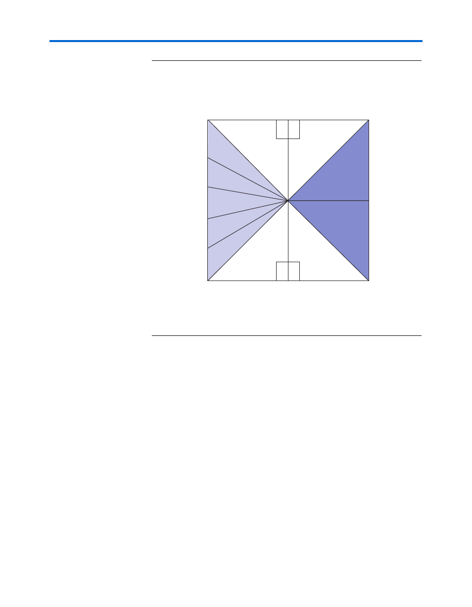
Figure 2–4. Stratix II GX Device I/O Mapping Resources
illustrates the clocking resources on both the EP2SGX90FF1508
and the EP2SGX130GF1508 devices. The parenthetical text refers to
board-level signals as they relate to specific clock pin names noted in both
the Quartus
®
II Development Software Handbook and the Stratix II GX Device
Handbook.
B4
B9
6
B11
6
B3
B7
B8
1.8 V
1.8 V
DDR2 (SSTL 18)
Flash (CMOS)
DDR2 (SSTL 18)
Flash (CMOS)
QDRII (HSTL 18)
Flash (CMOS)
GigE PHY (CMOS)
QDRII (HSTL)
Flash (CMOS)
1.8V
SFP Port A
SFP Port B
HSMC Port A
2.5 V
HSMC Port A
(LVDS/CMOS)
2.5 V
HSMC Port B
(LVDS/CMOS)
HSMC Port B
PCIe Edge
Lanes [0:3]
PCIe Edge
Lanes [4:7]
HSMC Port B
(2SGX130 only)
2.5V
B2
B1
B13
B14
B15
B16
B17
6
B10
6
B12
Note:
Figure is package-top referenced.