3front panel controls, Rear panel controls – Alto Professional HPA6 User Manual
Page 3
3
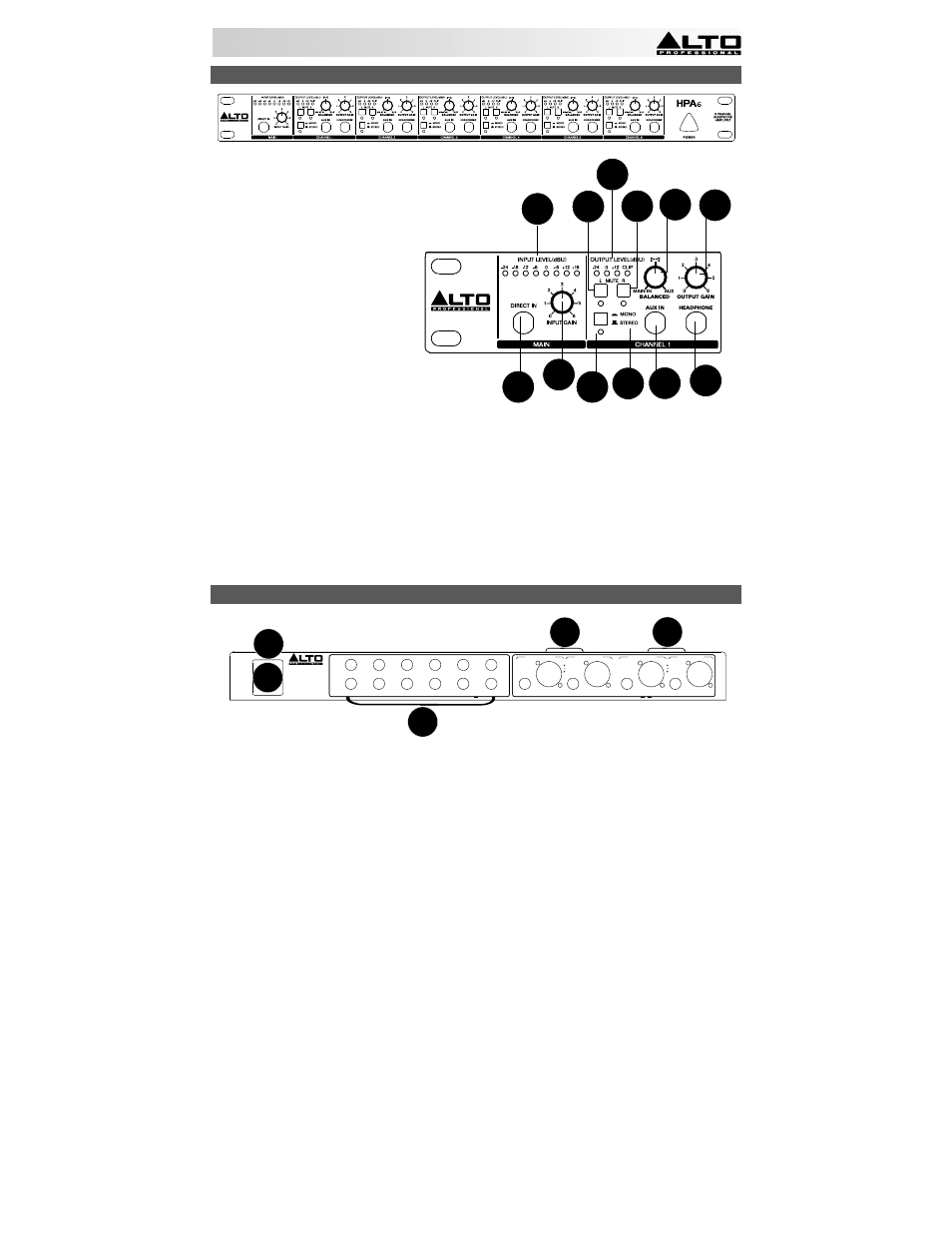
FRONT PANEL CONTROLS
1. Direct input - Feeds an external
audio source directly into the main
signal path.
2. Input gain control - Controls the
signal level going to the Main or
Direct Inputs.
3. Input level meter - Displays the
signal level coming from Main/Direct
Inputs. For the best quality of input
signal, the LED should range from
+6 to +18 dBu. If the Clip LED (in
the Output Level Meter) is always
on, reduce the input level using the
input gain control.
4. Aux input - Provides a separate
stereo input signal which can be
mixed with the Main/Direct Input
signal.
5. L mute switch - Mutes the left input
signal.
6. R mute switch - Mutes the right input signal.
7. Mode switch - Switches the operational mode between mono and stereo.
8. Mono LED - This LED lights up when the unit is in mono mode. When the LED is off, the unit is in stereo
mode.
9. Headphone output - 1/4" TRS phone jack used to output the
signal of the individual channel. There are
also 12 additional headphone outputs (two for each channel) on the rear panel.
10. Balance control - Sets the amount of the signal coming from Aux Input and Main/Direct Input. When the
Aux Input is not in use, it will regulate the stereo imaging of the input signal. When a signal is fed into the
Aux Input, the balance control will regulate the ratio of the Main Input (or Direct In) and the Aux Input
signals.
11. Output gain control - Adjusts the output level of the individual channel.
12. Output level meter - Displays the output signal level. If the Clip LED lights up, turn down the input gain
control and/or the individual output gain control
to avoid distortion.
REAR PANEL CONTROLS
13. Fuse holder -
If the fuse blows, replace it with a fuse of the same type.
14. Power Connector - Use the included power cable to connect this connector to a power source.
Please
check the voltage accepted by the unit and the voltage available from your power source before
connecting it.
15. Main input connectors - Balanced 1/4" TRS and XLR connectors used to input the stereo signal.
16. Main output connectors - Balanced 1/4" TRS and XLR connectors used to output the main signal. Use
these connectors to link several headphone amplifiers together.
17. Headphone out (1-12) - These are 12 additional headphone outputs (two for every channel) wired in
parallel with the output available on the front panel.
3
5
6 10 11
12
1 2
4
7
8
9
TIP:
L- CHANNEL
RING:
R- CHANNEL
MIN. LOAD
100 OHMS
6
6
5
5
4
4
3
3
2
2
1
1
HEADPHONE OUT
MAIN OUTPUT RIGHT
MAIN OUTPUT LEFT
TIP/PIN 2
RING/PIN 3
SLEEVE/PIN 1
TIP/PIN 2
RING/PIN 3
SLEEVE/PIN 1
MAIN INPUT RIGHT
MAIN INPUT LEFT
14
13
15
16
17