Applied Motion 1035D User Manual
Page 7
-7-
-10-
Motor
Size
Winding
Max Torque
Current
Number
inches
Connection
oz-in
Amps
5014-842
1.38 x 1.38 x 1.57
4 lead
22
1.0
5017-006
1.65 x 1.65 x 1.34
center-end
10
1.0
5017-009
1.65 x 1.65 x 1.54
center-end
17
0.8
5017-013
1.65 x 1.65 x 1.85
center-end
24
0.8
HT17-068
1.65 x 1.65 x 1.30
parallel
22
1.0
HT17-072
1.65 x 1.65 x 1.54
parallel
34
1.0
HT17-076
1.65 x 1.65 x 1.85
parallel
54
1.0
4023-839
2.22 x 2.22 x 1.5
center-end
35
1.0
4023-819
2.22 x 2.22 x 2.0
center-end
56
1.0
HT23-393
2.22 x 2.22 x 1.54
parallel
34
1.0
HT23-396
2.22 x 2.22 x 2.13
parallel
110
1.0
HT23-399
2.22 x 2.22 x 2.99
parallel
140
1.0
Recommended Motors
The following motors from Applied Motion Products are recommended for
use with the 1035D. All motors in the list have been tested with the 1035D.
Dynamic torque data is available.
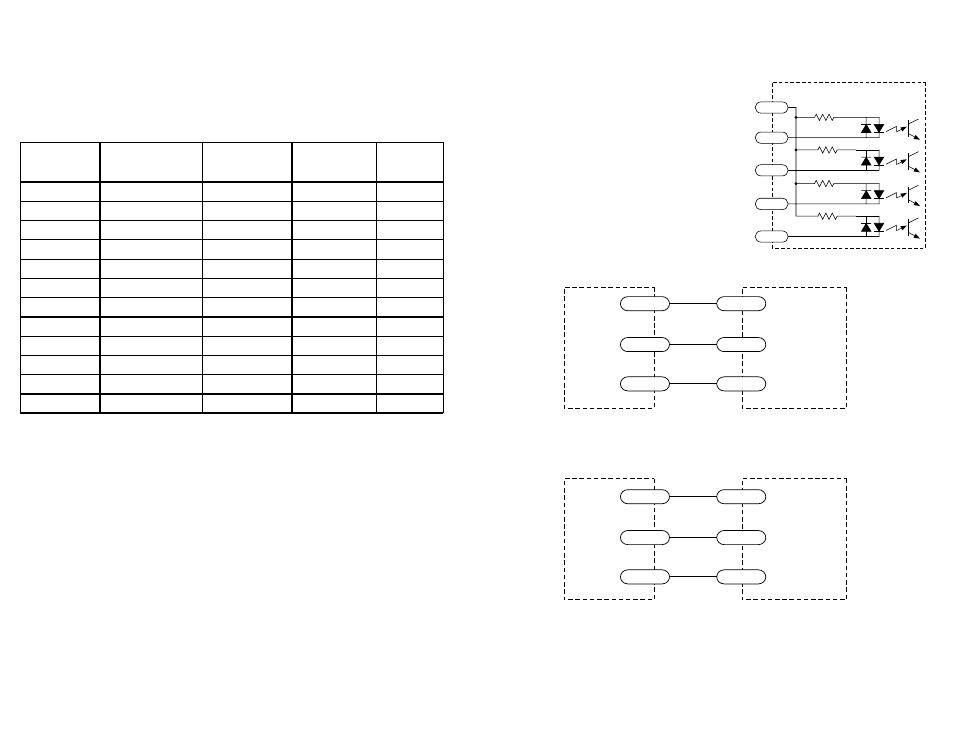
Connecting A Pulse Source
The 1035D inputs contain optical isolation
circuitry to prevent the electrical noise inherent
in switching amplifiers from interfering with your
circuits.
Optical isolation also allows the 1035D to accept
step and direction signals ranging from 5 to 24
volts. Furthermore, the input signals can be
sourcing (PNP) or sinking (NPN), depending on
how you connect the COM terminal.
A schematic diagram of the input circuit is at the
right. The wiring diagrams below show how to
connect the drive to various pulse sources.
2200
2200
inside 1035D
COM
STEP1
DIR1
2200
2200
STEP2
DIR2
+5 VDC
STEP–
DIR–
1035D
Si-100
1035D
SI-1
COM
STEP
DIR
Connecting Applied Motion Si-100
+5 VDC
STEP
DIR
COM
STEP
DIR
Connecting Applied Motion SI-1