Applied Motion 3540MO User Manual
Quick setup guide 3540mo, Speed control from a 0 to 5 volt analog signal, Connecting the power supply
Flip Over
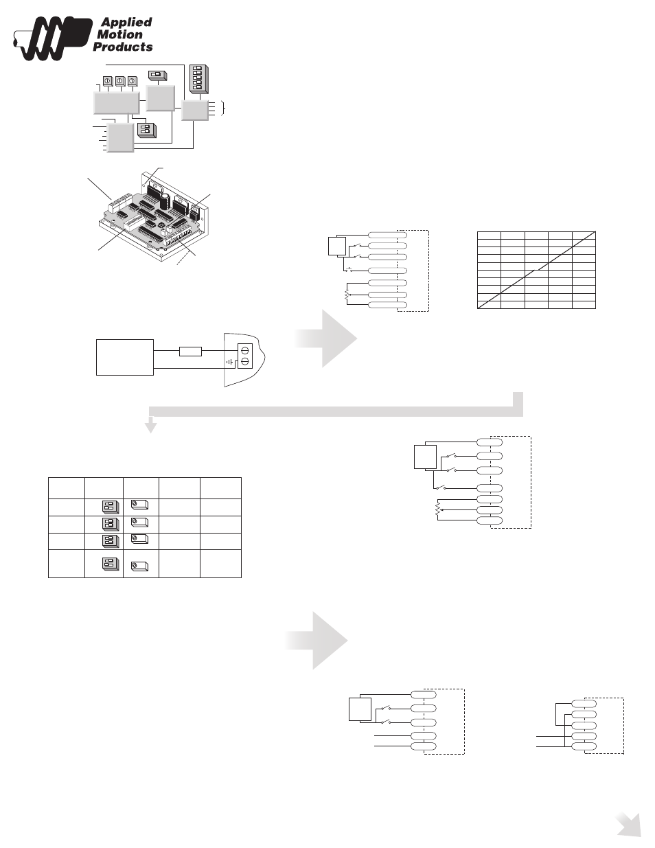
Typical wiring for Oscillator Mode using external speed Control pot
Speed Control from a 0 to 5 Volt Analog Signal
In oscillator mode, the 3540MO can rotate the motor a speed proportional to an
analog voltage. The voltage must be applied to the WPR terminal. The direction of
rotation will be controlled by the digital DIR input and the motor can be stopped
either by setting the analog input voltage to 0 or by turning the digital RUN signal
off.
To use the 3540 MO in this mode, set switch #1 away from the JOYSTICK label,
and set switch #2 toward the EXT SPEED label.
DRAWING...........
The HI SPEED pot sets the maximum speed (the motor speed when the analog
signal is at 5 volt DC). The range is 0 - 25 rev/sec.
Wiring diagrams and a plot of speed vs voltage are shown below.
12–42V
motor
supply
12-42 VDC
+
–
4A slow
blow
fuse
DO NOT REVERSE WIRES - THIS WILL DAMAGE THE DRIVE
Quick Setup Guide
3540MO
TO DOWNLOAD
Connecting the Power Supply
run
direction
common
ext
speed
input
12-42 VDC
hi/lo speed
current
0.4 to 3.5
A/phase
ext speed
joystick
A+
A–
B+
B–
to
motor
enable
tach out+
tach out-
50% idle
accel
LO
speed
HI
speed
Microstep
Sequencer
MOSFET
Amplifier
Optical
Isolation
Digital Oscillator
&
Joystick Interface
power connector
• DC power supply
• motor
trim pots
• accel/decel rate
• low speed
• high speed
input connector
• run/stop (cw limit)
• dir (ccw limit)
• high/low speed select
• amp enable
• ext speed pot/joystick
• tach out
mounting hole (1 of 6)
DIP switches
• motor current
• idle current reduction
• joystick mode
• ext speed mode
Always use the blue & white
Applied Motion screwdriver
with this connector. Larger
screwdrivers may remove the
plastic dimples that prevent
the screws from falling out.
Modes of Operation
Note: We refer to an input as being ON when current is flowing
through the input. A signal is OFF when no current is flowing. An
input is OFF when COM and the input terminal are at the same voltage,
or when the input is left unconnected (open).
The 3540 MO features two modes of operation.
Joystick mode
Joystick mode is set by moving switch #1 toward the word “Joystick”. Switch #2
(EXT SPEED) has no effect in Joystick mode.
Joystick mode - speed and direction are determined by the voltage applied to the WPR
(wiper) terminal. 2.5 volts is “stopped” (no speed). Increasing the WPR voltage
toward 5 volts results in forward motion: speed increases with voltage. Decreasing
the WPR voltage from 2.5 toward 0 results in reverse motion, with speed increasing
as voltage decreases. The SPD (speed) input selects speed range. LO SPEED and HI
SPEED pots adjust the 2 speed ranges.
EXT SPD=ON speed adjusted by LO SPEED trimpot - range up to 5 rev/sec
EXT SPD=OFF speed adjusted by HI SPEED trimpot - range up to 25 rev/sec
In joystick mode, limit switches can be connected to the 3540 MO.
Refer to the full manual - available from the website for connection details.
Oscillator mode
Oscillator mode is selected by moving switch #1 away from the word Joystick.
Thespeed can be controlled by on-board potentiometers and/or
by an external analog voltage. RUN input starts and stops the motor. DIR input
controls direction of rotation. SPD input selects the speed range.
If the motor is wired according to the motor wiring section,
Motor speed and the function of the RUN input can be determined from the
following table.
SPD (speed) input selects speed range. LO SPEED and HI SPEED pots adjust the 2
speed ranges.
EXT SPD=ON speed adjusted by LO SPEED trimpot - range up to 5 rev/sec
EXT SPD=OFF speed adjusted by HI SPEED trimpot - range up to 25 rev/sec
If switch #2 is toward the words EXT SPEED, then the high speed is proportional to
the voltage applied to the WPR terminal, and is trimmed by the HI SPEED pot. You
can connect an external 1K - 5K pot to the WPR, CW and CCW terminals, or you can
apply a 0 to 5 volt analog signal to the WPR terminal (ground your analog signal to the
CCW pin.) The high speed range is 0 - 25 rev/sec (0 - 1500 rpm.) You can reduce the
range by turning down the HI SPEED pot.
When switch #2 is away from the EXT SPEED label, the high speed is set by the HI
SPEED pot and the WPR input does nothing.
Never apply more than 5 volts DC or less than 0 volts to the WPR pin.
In both operating modes, the accel/decel rate is set by the ACCEL pot. The
range is 1 to 250 rev/sec/sec.
5kW
joystick
joystick "fire" button
fwd
rev
3540 MO
COM
DIR (REV LIMIT)
RUN (FWD LIMIT)
SPD
CCW
WPR
CW
+
5-24
VDC
SUPPLY
-
rev limit switch
fwd limit switch
Typical wiring for Joystick Mode
0
1
2
3
4
5
-25
-20
-15
-10
-5
0
5
10
15
20
25
Speed vs Input Voltage
Joystick mode, SPD input off (or open)
HI SPEED pot at maximum
volts
volts
speed (rev/sec)
SPD
switch
speed set
when RUN
when RUN
input
#2
by
goes ON
goes OFF
ON
accel to speed instant stop
ON
accel to speed instant stop
OFF/open
accel to speed decel to stop
OFF/open
accel to speed decel to stop
ext speed
joystick
ext speed
joystick
ext speed
joystick
ext speed
joystick
LO SPEED
LO SPEED
HI SPEED
HI SPEED
WPR input
trimmed by
5kW
pot
speed switch (closed=lo speed)
cw
ccw
3540 MO
COM
DIR
RUN
SPD
CCW
WPR
CW
+
5-24
VDC
SUPPLY
-
direction switch
run/stop switch
(closed=run)
Wiring for Speed Control by 0 - 5 Volt Analog Signal
(Direction Control by Digital Signal or Switch)
0 - 5V speed signal
signal return
3540 MO
COM
DIR
RUN
CCW
WPR
+
5-24
VDC
SUPPLY
-
direction switch
run/stop switch
(closed=run)
Wiring for Speed Control by 0 - 5 Volt Analog Signal
(Unidirectional Rotation)
0 - 5V speed signal
signal return
3540 MO
COM
RUN
CCW
WPR
CW
Doc 920-0017B - 8/27/12