Choosing a power supply, Mounting the drive, Smooth flat surface #4 screws – Applied Motion 3540MO User Manual
Page 2: Technical specifications, Idle current reduction, Microstepping, Connecting the motor, Tach output, Connecting digital inputs and limit switches
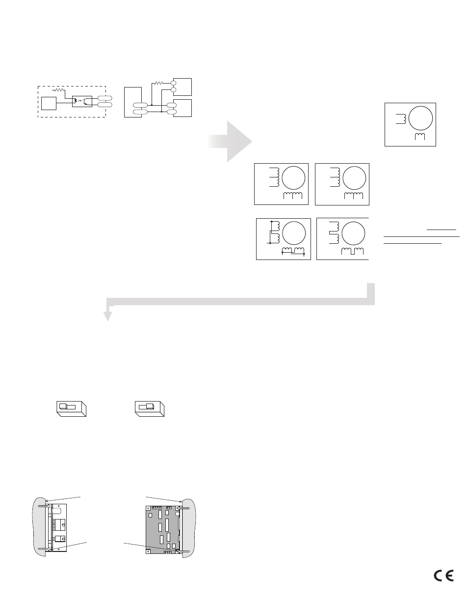
Choosing a Power Supply
To find out how to choose a power supply refer to the tech notes on our website.
Mounting the Drive
To operate the drive continuously at maximumpower you must properly mount it on
a heat sinking surface with a thermal constant of no more than 4°C/watt. Often, the
metal enclosure of your system will make an effective heat sink.
smooth flat surface
#4 screws
wide side mount
narrow side mount
Technical Specifications
Amplifiers
Dual, bipolar MOSFET H-bridge, pulse width modulated
three state switching at 20kHz. 12-42 VDC input.
0.4 - 3.5 amps/phase output current, switch selectable
in 0.1 A increments. 122 watts maximum output power.
Automatic idle current reduction (switch selectable),
reduces current to 50% of setting after one second.
Minimum motor inductance is 1 mH.
Inputs
Run/stop (cw limit), direction (ccw limit), hi/lo speed and
enable inputs are optically isolated, 5-24V logic. 3 - 15 mA
input current. 2200 ohms input impedance. Can be
configured for sinking or sourcing signals.
Recommended external pot/joystick resistance: 1K - 5K
Joystick dead zone: ± 80 mV.Potentiometer/analog signal
dead zone: 40 mV.
Recommended Maurey Instrument Corp., Chicago, IL (773)581-4555
Joystick
JS31462S5T3 (2 axis) or SAJ2515-F-502 (1 axis)
Speed Ranges LO speed range: 0 - 5 rev/sec
HI speed range: 0 - 25 rev/sec
Accel/decel range: 1 to 250 rev/sec/sec
Tach Output
Phototransistor, open collector, open emmiter.
24 volts max, 20 mA max.100 pulses per motor revolution,
50% duty cycle (square wave).
Physical
Mounted on 1/4 inch thick black anodized aluminum
heat transfer chassis. 1.5 x 3.0 x 4.0 inches overall. Power
on red LED. Ambient temperature range: 0 - 70 C.
Connectors
European style screw terminal blocks.
Power Supply & Motor: 6 position. Wire size: AWG 12 - 28.
Signal Input: 10 position. Wire size: AWG 16 - 28.
Microstepping
CE Mark 1/64 step (12,800 s/r) with 1.8 motor. Pure sine
waveform.
CE Mark
Complies with EN55011A and EN50082-1(1992).
Idle Current Reduction
Your drive is equipped with a feature that automatically reduces the motor
current by 50% anytime the motor is not moving. . Idle current reduction is
enabled by sliding switch #4 toward the 50% IDLE label,as shown in the
sketch below. Sliding the switch away from the 50% IDLE label disables the
reduction feature
50% IDLE
4
4
50% IDLE
Idle Current Reduction
Selected
No Current Reduction
Microstepping
The 3540 MO divides each full step into 64 microsteps, providing 12,800 steps
per revolution for precise positioning and smooth motion.
Connecting the Motor
STEP motors have 4, 6 or 8 leads , these are
wired to 4 connections on the drive in various
combinations.
Motors will perform differently according the
way it is connected, to find out more about the
differnet way of connecting your motor , see the
technotes or FAQs on our website.
Warning: When connecting
the motor to the driver, be
sure that the motor power
supply is off. Secure any
unused motor leads so that
they can’t short to anything.
Never disconnect the motor
while the drive. Never con-
nect motor leads to ground
or to a power supply!
A+
A–
B+
B–
4
lead
motor
Red
Blue
Yellow
White
4 Leads
A+
A–
NC
B+
B–
NC
6
lead
motor
Red
Black
Red/
Wht
Green
Grn/Wht
White
6 Leads
Series
Connected
A+
A–
NC
B+
B–
NC
6
lead
motor
Grn/Wht
White
Green
Red
Red/
Wht
Black
6 Leads
Center Tap
Connected
A+
A–
B+
B–
8
lead
motor
8 Leads
Series
Connected
Orange
Org/Wht
Blk/Wht
Black
Red Red/
Wht
Yel/
Wht
Yellow
A+
A–
B+
B–
8
lead
motor
Orange
Org/
Wht
Blk/Wht
Black
Red
Red/Wht
Yel/
Wht
Yel
low
8 Leads Parallel Connected
A+
A–
B+
B–
8
lead
motor
Orange
Org/
Wht
Blk/Wht
Black
Red
Red/Wht
Yel/
Wht
Yel
low
8 Leads
Parallel
Connected
Tach Output
The Tach Out signal is provided for measuring the motor speed. It generates
100 pulses per revolution, so if you connect a frequency counter, the speed
reads out in revs/second with two decimal places. The schematic diagram of
the Tach Out optoisolation circuit is shown below.
Do not connect the Tach output to more than 24VDC.
The current into the Tach+ terminal must not exceed 20 mA.
Internal Tach Circuit
330W
internal
tach
signal
+5V
TACH–
TACH+
Optoisolator
NEC PS2501 or equiv.
inside 3540 MO
Connecting Tach Output
to a Frequency Counter
4700W
5 - 24V
DC
Power
Supply
TACH–
TACH+
–
+
Freq
Counter
3540 MO
GND
IN
Connecting Digital Inputs and Limit Switches
You must supply 5-24 volts DC to supply current to the LEDs on the input side
of the opto-isolators.Your controlling logic must be capable of sinking or sourc-
ing at least 3 mA at 5 volts and 10 mA at 24 volts to control each drive input.
Sinking Circuits (NPN) - If your output devices prefer to sink current, then
connect the COM terminal to your positive power supply. If you are using a
TTL circuit to drive the 3540 MO, connect the COM terminal to your 5 volt bus.
No ground connection is needed. If you are using a PLC or proximity sensor,
you’ll need a power supply.
Sourcing circuits (PNP) - If your output devices can only source current (some
PLC outputs are this way), connect the COM terminal to the ground of the DC
power supply that powers your output circuits Note: We refer to an input as
being ON when current is flowing through the input. A signal is OFF when no
current is flowing. An input is OFF when COM and the input terminal are at the
same voltage, or when the input is left unconnected (open).
The ENABLE input allows the user to turn off the current to the motor by
setting this signal on. The logic circuitry continues to operate, so the drive
“remembers” the step position even when the amplifiers are disabled. If you
have no need to disable the amplifiers, you don’t need to connect anything to
the ENABLE input.