Applied motion products, inc, 2035 o – Applied Motion 2035 User Manual
Page 2
Check your wiring carefully before turning on the power supply!
Current Reduction
The 2035 and 2035 O drives include a feature that automatically reduces the motor cur-
rent by 50% when the motor is not moving. This is known as idle current reduction.
If you want full current all the time, move the switch away from the 50% IDLE label.
Using a Remote Speed Control Potentiometer
The 2035 O step motor driver includes an analog signal input connector that can be
used to control the oscillator speed externally. Normally, an on board potentiometer
controls the speed.
You will need:
• a 10k to 100k ohm linear potentiometer. A multiturn type is recommended.
• a shielded, three wire cable
To install the external pot:
• move switch #1 toward the EXTSPEED label. That disconnects the on board
pot.
• wire your pot to the 2035 O:
the potentiometer wiper connects to the WPR terminal
the potentiometer CW terminal connects to the CW terminal
the third pot terminal connects to the CCW terminal
the cable shield connects to the CCW terminal
With this arrangement, speed will increase as you turn the external pot clockwise.
The frequency range will be 0 to 5000 steps per second.
The on board trimpots will still control acceleration and declerations times. Turning the
pots clockwise makes the acceleration and deceleration faster (i.e. reduces the time to
or from speed).
Mounting the Drive
You can mount your drive on the wide or the narrow side of the chassis. If you mount
the drive on the wide side, use #4 screws through the four corner holes. For narrow
side mounting applications, you can use #4 screws in the two side holes.
Never use your drive in a space where there is no air flow or where other devices cause
the surrounding air to be more than 50°C. Never put the drive where it can get wet or
where metal particles can get on it.
smooth flat surface
#4 screws
wide side mount
narrow side mount
Technical Specifications
Amplifiers
Dual, bipolar H-bridge, pulse width modulated switching at 20kHz. 12-35 VDC
input. 0.125 - 2.5 amps/phase output current,switch selectable in 0.125 A
increments. 70 watts maximum outputpower. Automatic idle current reduction,
reduces current to 50%of setting after one second
Oscillator (O suffix)
0 to 5000 steps per second. Linear acceleration and deceleration, individually
adjustable from 5 to 900 msec.
Inputs
Step, direction and enable, optically isolated, 5-24V logic. 2200 ohms input
impedance. Motor steps when STEP input turns off.
10 μsec minimum low pulse. 50 μsec minimum set up time for direction signal.
Step input is run/stop in oscillator mode. (0 =run, 1 = stop.)
Tach Output (O suffix)
Optically isolated. Uncommitted (open collector, open emitter)
phototransistor, 24V max, 20 mA max. One pulse per step.
Physical
Mounted on 1/4 inch thick black anodized aluminum heat transfer chassis. 1.5 x
3.0 x 4.0 inches overall. Power on LED.
Maximum chassis temperature: 70°C. Weight: 9 ounces (250 g).
Ambient temp range (operating): 0 - 70°C.
Connectors
European style screw terminal blocks.
Power Supply: 2 position.
Motor: 4 position.
Signal Input: 4 position (2035), 9 position (2035 O)
Max wire size: AWG 16.
Applied Motion Products, Inc.
404 Westridge Drive Watsonville, CA 95076
Tel (831) 761-6555 (800) 525-1609 Fax (831) 761-6544
Copyright 1998
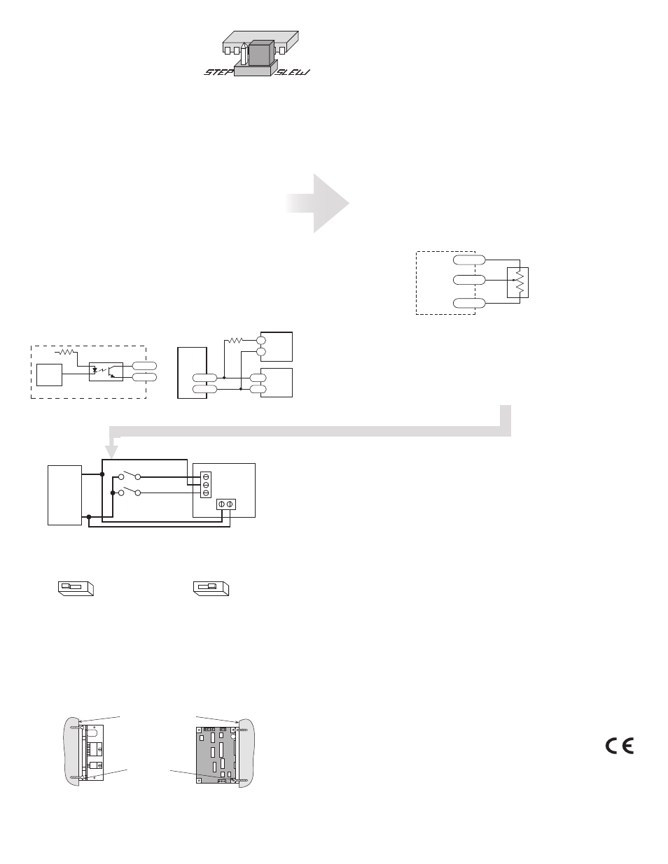
cw
external
pot
2035 O
CW
WPR
CCW
The Using Mechanical Switches with 2035 O Drive
The 2035 O was designed to be used with active logic and for that reason has
optically isolated inputs. To activate the optoisolators a small, but not insignificant amount
of current at 5 to 24 volts DC is required.
In some applications, step motors and drives are used with mechanical switches only and
there is no readily available source of 5 - 24 volts.
In these instances, the motor power supply can be used if it does not exceed 24VDC. The
recommended wiring diagram is shown below.
2
50% IDLE
50% Idle Current
50% IDLE
No Idle Current Reduction
2
Motor
Power
Supply
12-24
VDC
+
-
Run/Stop switch (closed=run)
Direction
switch
2035 O
STEP C
OM DIR
+VDC-
Doc 920-0014 2/27/08
Choosing a Power Supply
To find out how to choose a power supply refer to the tech notes on our website.
Using the Oscillator
Drives with an O suffix are equipped with internal
pulse generators that you can use to drive the
motor. To set the drive to oscillator mode, simply
find the jumper located near the center of the
printed circuit board and move it to the SLEW
setting. The figure at the right shows the proper
setting of the jumper.
The oscillator is activated by driving the STEP input low. The frequency of step
pulses will increase linearly, accelerating the motor until it reaches a preset slews-
peed. The motor will remain at this speed until the STEP input is driven high. The
step pulse frequency then decreases linearly, decelerating the motor and load to
rest.
To change the slew speed, locate the trimpot labeled SPEED. By turning the
brassscrew you can raise or lower the speed within a range of 0 to 5000 steps per
second. Turning the screw clockwise makes the motor run faster.
The acceleration and deceleration rates can also be adjusted using the trimpotsla-
beled ACCEL and DECEL. The range of accel and decel time is 5 to 900 millisec-
onds. Turning the screw clockwise makes the motor accelerate and decelerate
faster.
The ACCEL and DECEL pots are single turn, so don’t try to turn them
too far.
Tach Output
The Tach Out signal is provided for measuring the motor speed. It generates one
pulse per motor step. The schematic diagram of the Tach Out optoisolation circuit
is shown below.
Do not connect the Tach output to more than 24VDC.
The current into the Tach+ terminal must not exceed 20 mA.
Internal Tach Circuit
330W
internal
tach
signal
+5V
TACH–
TACH+
Optoisolator
NEC PS2501 or equiv.
inside 2035 O
Connecting Tach Output
to a Frequency Counter
4700W
5 - 24V
DC
Power
Supply
TACH–
TACH+
–
+
Freq
Counter
2035 O
GND
IN