Applied Motion 3535 User Manual
Page 2
Doc 920-0013 - 2/26/08
In some applications, step motors and drives are used with mechanical
switches only and there is no readily available source of +5 volts.
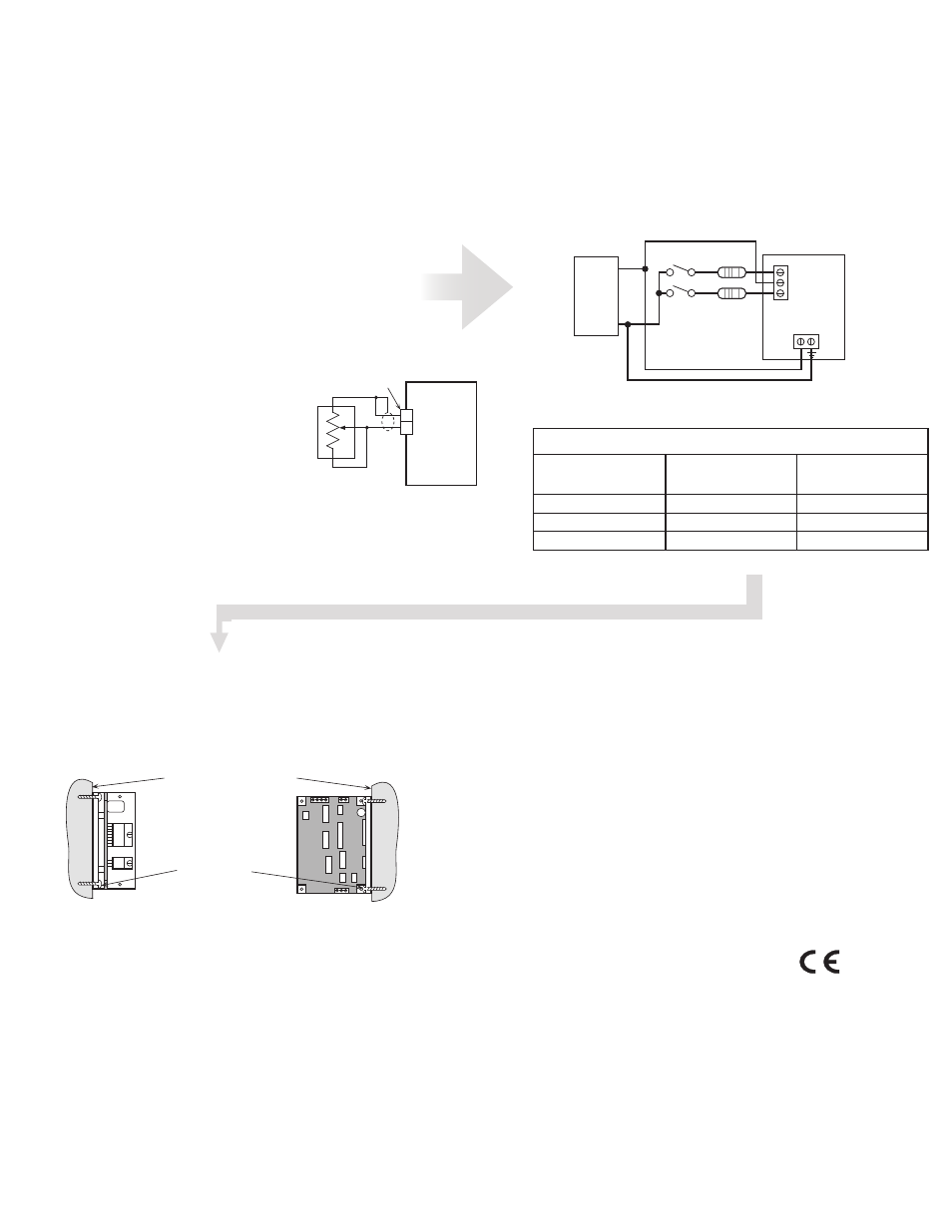
In these instances, the 12-35 VDC motor power supply can be used with ad-
ditional dropping resistors to power the opto LEDs. The recommended wiring
diagram is shown on page 11. Table I lists the appropriate resistor value to
use for a given power supply voltage. 1/4 watt or larger resistors should be
used.
Please do not to reverse the wiring, as damage to the LEDs will result
rendering the drives inoperable. Check your wiring carefully before
turning on the power supply!
Using Remote Speed Control Potentiometer
The latest revision of model 3535 O step motor drive includes an analog signal input
connector that can be used to control the oscillator speed externally. Normally, an on
board potentiometer controls the speed.
You will need:
a 100kW or 200kW linear potentiometer. A multiturn type is recommended.
a two pin female connector compatible with .025 inch square pins on .100”
centers. AMP type MTA-100 is one type that works well
a shielded, two wire cable
To install the external pot:
• locate the connector on the 3535 O labelled ÒXSPD.Ó It can be found between the
signal connector and the three blue potentiometers.
• turn the screw on the blue SPEED potentiometer 15 turns counterclockwise. If you
don’t do this, the external potentiometer will not provide the correct speed range.
• prepare a cable with your pot on one end and the connector on the other end:
the potentiometer wiper connects to pin 2
the potentiometer CW terminal connects to pin 1
the third pot terminal connects to the wiper
the cable shield connects to the CW pot terminal
With this arrangement, speed will increase
as you turn the external pot clockwise.The
frequency range for the 200k ohm pot will be
600 to 5000 steps per second. The frequency
range for the 100k ohm pot will be900 to
5000 steps per second. The on board trim-
pots will still control acceleration and declera-
tion times. Turning the pots clockwise makes
the acceleration and deceleration faster (i.e.
reduces the time to or from speed).
Using Mechanical Switches with 3535-O Drive
The 3535-O was designed to be used with active logic and for that reason are optically
isolated. To activate the optoisolators a small, but not insignificant amount of current at
+5 volts DC is required.
•
•
•
cw
3535 O
Drive
external
pot
XSPD
connector
1
2
Motor
Power
Supply
12-35
VDC
+
–
R
R
Run/Stop switch
(closed=run)
Direction
switch
3535 O
drive
STEP +5 DIR
12-35VDC
Supply
R
Supply
R
Supply
R
Voltage
Ohms
Voltage
Ohms
Voltage
Ohms
12
1200
21
3000
30
4700
15
1800
24
3600
33
5100
18
2400
27
4200
35
5600
Table I: External Dropping Resistors
Choosing a Power Supply
To find out how to choose a power supply refer to the tech notes on our website.
Mounting the Drive
To operate the drive continuously at maximum power you must properly mount it on
a heat sinking surface with a thermal constant of no more than 4°C/watt. Often, the
metal enclosure of your system will make an effective heat sink.
smooth flat surface
#4 screws
wide side mount
narrow side mount
Technical Specifications
Amplifiers
Dual, bipolar H-bridge, pulse width modulated switching at 20kHz. 12-35 VDC
input. 0.4 - 3.5 amps/phase output current, switch selectable in 0.1 A incre-
ments. 122 watts maximum output power. Automatic idle current reduction,
reduces current to 50% of setting after one second
Oscillator (O suffix)
400 to 5000 steps per second. Linear acceleration and deceleration, individu-
ally adjustable from 5 to 900 msec.
Inputs
Step, direction and enable, optically isolated, 5V logic. 5mA/signal, sink
requirement. Motor steps on rising edge of stepline. 10 µsec minimum low
pulse. 50 µsec minimum set up time for direction signal. Step input doubles as
run/stop in oscillator mode. (0 = run, 1 = stop.)
Physical
Mounted on 1/4 inch thick black anodized aluminum heat transfer chassis.
1.5 x 3.0 x 4.0 inches overall. Power on LED.
Maximum chassis temperature: 70° C.
Connectors
European style screw terminal blocks. Motor: 4 position. Signal Input: 4 posi-
tion. DC Input: 2 position.
CE Mark.
Complies with EN55011A and EN50082-1(1992).
Applied Motion Products
404 Westridge Dr.
Watsonville, CA 95076
tel / 831-761-6555
fax / 831-761-6544
www.applied-motion.com
Host Command Reference (Version C1)
6/6/06
Applied Motion Products
404 Westridge Dr.
Watsonville, CA 95076
tel / 831-761-6555
fax / 831-761-6544
www.applied-motion.com