Step 3, Step 5, Step 4 – Applied Motion ST10-Q-EE User Manual
Page 2: St5/10-q quick setup, 0007 rev e, Encoder, Db25, Optional
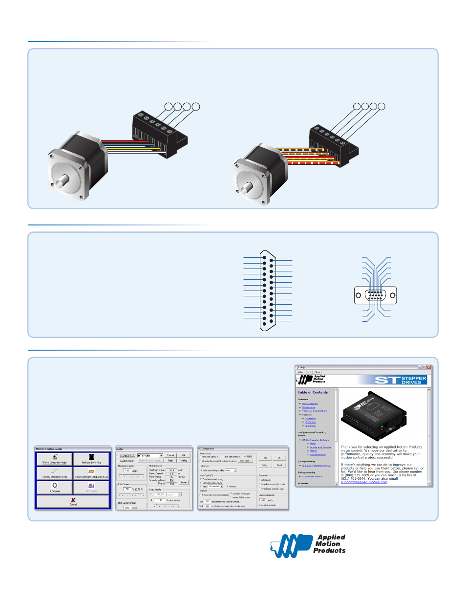
Step 3
If you have any questions or comments, please call
Applied Motion Products Customer Support:
(800) 525-1609, or visit us online:
www.applied-motion.com.
404 Westridge Dr.
Watsonville, CA 95076
Tel: 800-525-1609
Fax: 831-761 -6544
www.applied-motion.com
a)
Apply power to the drive.
b)
Follow the configuration instructions in the ST Configurator™ help screens.
The ST Configurator™ software can be used to set up your drive for
operation in several different modes including: pulse & direction, analog
velocity, SCL, and Q programming. ST Configurator™ includes a self test
option (under the Drive menu) to verify that the motor and power supply
are correctly wired and configured.
c)
Use Q Programmer™ to build and test your program.
Step 5
redblue
yellow
white
A+ A- B+ B-
orange+blk/wht
blac
k+org/wht
red+y
el/wht
yello
w+red/wht
A+ A- B+ B-
Figure 2
Figure 1
920-0007 rev E
Warning - If you are using a non-Applied Motion motor, do not connect the motor until after you have configured the drive
for your motor. Refer to Step 5.
Connect the drive to the motor. Four lead motors can be connected in only one way, as shown in Figure 1.
We recommend that eight lead motors be connected in parallel, as shown in Figure 2.
If using a non-Applied Motion Products motor, please refer to your motor specs for wiring information.
a)
Connect the I/O
b)
Connect the Encoder (optional)
c)
Connect to RS485 or Ethernet network (optional)
Step 4
X COMMON
X3 / Enable
X5 / CW JOG
X4 / Alarm Reset
Analog IN
Analog IN
X2 / DIR -
X2 / DIR +
X1 / STEP+
X1 / STEP -
GND
GND
X8/CCW LIMIT -
X8/CCW LIMIT+
X7/CW LIMIT -
X7/CW LIMIT+
Y4 -
Y4+
+5V OUT
Y COMMON
Y3 / FAULT
Y2 / MOTION
Y1 / BRAKE
18
17
16
15
14
13
12
11
10
9
8
7
6
5
4
2
3
1
19
20
21
22
23
24
25
X6 / CCW JOG
IN/OUT - ST5/10 - Q/Si
Z+ (5)
NC (10)
B- (4)
NC (9)
B+ (3)
NC (13)
NC (14)
NC (15)
(12) NC
(11) NC
(6) Z-
(1) A+
(7) +5VDC 200mA
(2) A-
(8) GND
PC GND
PC TX-/RX- or B
PC TX+/RX+ or A
+RX- +TX- GND
Drive 1
Drive 2
Drive 3
+RX- +TX- GND +RX- +TX- GND
PC GND
PC RX-
PC RX+
PC TX-
PC TX+
+RX- +TX- GND
Drive 1
Drive 2
Drive 3
+RX- +TX- GND +RX- +TX- GND
ENCODER
*OPTIONAL
DB25
ST5/10-Q Quick Setup