Setting up the drive, Step 3 - selecting the motor, Step 4 - selecting current – Applied Motion STR2 User Manual
Page 2: Step 5 - load inertia step 7 - self test, Step 8 - user manual, Step 6 - step resolution
If you have any questions or comments, please call
Applied Motion Products Customer Support:
(800) 525-1609, or visit us online:
www.applied-motion.com.
404 Westridge Dr.
Watsonville, CA 95076
Tel: 800-525-1609
Fax: 831-761 -6544
www.applied-motion.com
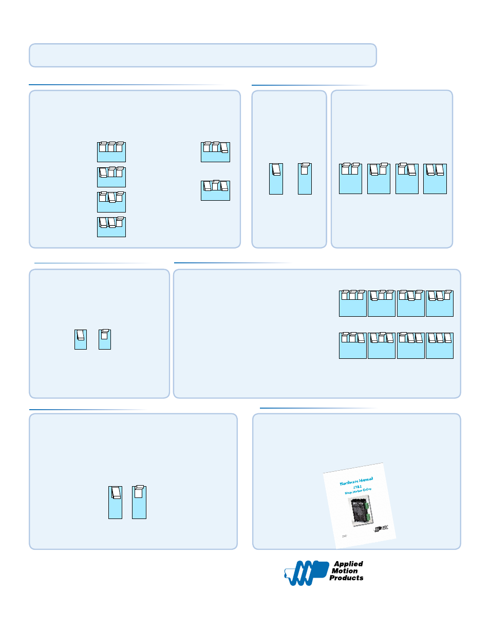
Step 3 - selecting the motor
Motor selection is done with the DIP switch block on the
narrow face of the drive. These switches are referred to
as B1 - B3 in the STR2 Hardware Manual.
Setting up the Drive
1 2 3
MOTOR
HT08-020/021
HT11-012/013
5014-842
HT17-068
1 2 3
1 2 3
1 2 3
1 2 3
1 2 3
MOTOR
HT17-271
HT17-275
HT23-595
HT23-598
HT23-601
Step 4 - selecting current
Switches A4 and A5 set the
running current to 70%, 80%,
90% or 100% of the motor’s
rated maximum current.
3
50%
3
90%
Switch A3 sets
the idle current to
either 50% or 90%
of the selected
running current.
4 5
100%
4 5
90%
4 5
80%
4 5
70%
Switch B4 chooses between two
load inertia ratio ranges.
This information is used in the
anti-resonance configuration.
A full user manual for the STR is available for download
from our web site. This contains full details on setup,
wiring and installation.
www.applied-motion.com/support
Step 5 - load inertia
Step 7 - self test
The STR has a built in Self Test function. If switch A1 is
moved to the ON position the drive will automatically rotate
the motor back and forth, two turns in each direction. This
feature can be used to confirm that the motor is correctly
wired, selected and otherwise operational.
1
ON
1
OFF
SELF TEST
Step 8 - user manual
4
5-10X
4
0-4X
Switches A6 - A8 specify the drive’s micro-
step resolution
▪
200
▪
200 with microstep emulation (smooth)
▪
400
▪
400 with microstep emulation (smooth)
▪
2000
▪
5000
▪
12800
▪
20000
6 7 8
20000
12800
5000
2000
400
SMOOTH
400
200
SMOOTH
200
6 7 8
6 7 8
6 7 8
6 7 8
6 7 8
6 7 8
6 7 8
Step 6 - step resolution
920-0060 A
NOTE: DIP switch setting changes will only take effect at power up. If changes to the DIP switches
are made while power is applied, cycle power off then on for the new settings to take effect.