Step 3 - drive configuration, Node id bit rate, Step 4 - canopen bus wiring – Applied Motion STM17C-3CE User Manual
Page 2: Stm17c quick setup guide, 0045 a, Bit rate table, 5 pin connector
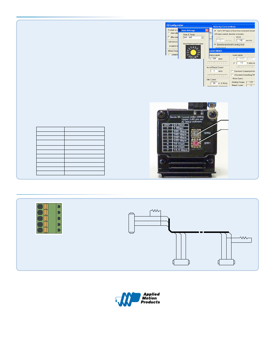
Step 3 - Drive Configuration
If you have any questions or comments, please call Applied Motion Products Customer Support:
(800) 525-1609, or visit us online at www.applied-motion.com.
404 Westridge Dr.
Watsonville, CA 95076
Tel: 800-525-1609
Fax: 831-761 -6544
www.applied-motion.com
a)
Apply power to the drive.
b)
Use ST Configurator™ to set up the motor current, limit switches, en-
coder functionality (if applicable) and Node ID. (See d)
c)
ST Configurator™ includes a self test option (under the Drive menu) to veri-
fy that the STM17C and power supply are correctly wired and configured.
d)
Set BitRate, Node ID
CANopen Bitrate - AMP CANopen drives have three settings, one for Bit Rate and two for Node ID. The
Bit Rate is configured using a ten-position switch. See Bit Rate table for the Bit Rate settings.
The Node ID is configured using a sixteen position switch to set up the lower four bits of the Node ID. The
upper three bits of the Node ID are set using ST Configurator™. Valid ranges for the Node ID are 0x01
through 0x7F. Node ID 0x00 is reserved in accordance to DS301 specification.
Note: The Node ID and Bit Rate are captured only after a power cycle, or after a network reset command
has been sent. Changing the switches while the drive is powered on will NOT change the Node ID until
one of these conditions has also been met.
e)
When configuration is complete, exit ST Configurator™, pow-
er off the drive and unplug the RS-232 cable.
920-0045 A
STM17C Quick Setup Guide
Switch Setting
Resultant Bit Rate
0
1 Mbps
1
800kbps
2
500 kbps
3
250 kbps
4
125 kbps
5
50 kbps
6
20 kbps
7
12.5 kbps
8
n/a
9
n/a
Bit Rate Table
Node ID
Bit Rate
GND
CAN_L
CAN_H
RXD
TXD
CAN_BUS
2
3
7
DSUB9
Female
CAN_L
GND
CAN_H
R Termination
120 Ohm nominal
CAN_L
GND
CAN_H
3
2
1
.1 Spacing
Spring Plug
R Termination
120 Ohm nominal
CAN_L
GND
CAN_H
3
2
1
.1 Spacing
Spring Plug
5 Pin Connector
Step 4 - CANopen Bus Wiring
▪
Wire to CAN network.
The Applied Motion Products STM17 drive uses a five-pin spring connec-
tor, that conforms to the DR303 cabling and connectors specification. The
connector should be wired in a daisy-chain configuration with a 120 Ohm
resistor used to terminate each end. Attach the drive to the CAN bus and
power-up the drive.