Applied Motion SV7-IP-EE User Manual
Sv7-ip quick setup guide, Requirements, Step 1
SV
SV7-IP Quick Setup Guide
Requirements
▪
A compatible servo motor.
▪
A small flat blade screwdriver for tightening the connectors (included).
▪
A personal computer running Microsoft Windows 98, NT, Me, 2000, XP, Vista, or 7.
▪
Quick Tuner™ software (version 2.2.17 or later) available at www.applied-motion.com/products/software.
▪
A CAT5 network cable (not included).
▪
For more detailed information, please download and read the SV7 Hardware Manual, available at www.applied-motion.com/support/manuals.
To begin, make sure you have the following equipment:
Step 1
a)
Download and install the QuickTuner™ software.
b)
Launch the software by clicking:
Start / Programs / Applied Motion Products / Quick Tuner
c)
Connect the drive to your network or PC using a standard CAT5 cable.
d)
Select an appropriate IP address using the rotary switch on the SV7-IP. For more information
about network configurations and IP addressing, please consult the SV7 Hardware Manual.
Step 2
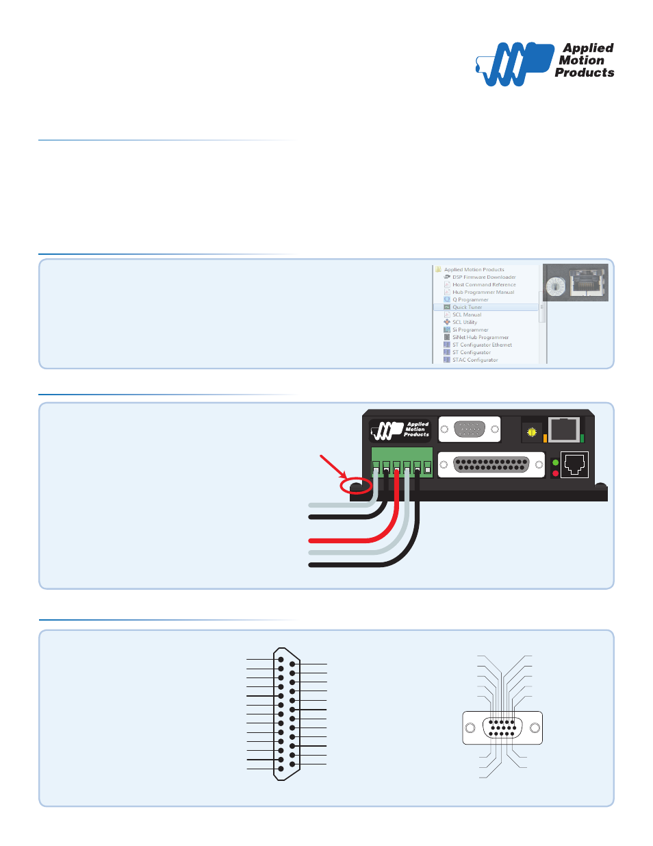
Wire the drive to the DC power source.
(Do not apply power until all connections to
the drive have been made)
Note, the SV7 drives accept DC power from
24-80 VDC.
For a non-Applied Motion Products motor, please
refer to your motor specs for wiring information.
Be sure to connect the motor case ground to the
grounding screw as indicated, leaving the last
pin on the motor/power connector unconnected.
4
3
21
0 F E D C B A 9
87
6
5
V+
V-
Motor A (or U) phase
Motor B (or V) phase
Motor C (or W) phase
Motor
Grounding
Screw
a)
Connect the I/O
b)
Connect the Encoder
▪
Applied Motion motor cables
are available with connectors
that mate directly to the
encoder connector on the drive.
Step 4
encoder Z+ (5)
Hall 1-(10)
encoder B- (4)
Hall 1+ (9)
encoder B+ (3)
Hall 3+ (13)
Hall 3- (14)
GND (15)
(12) Hall 2-
(11) Hall 2+
(6) encoder Z-
(1) encoder A+
(7) +5VDC 200mA
(2) encoder A-
(8) GND
Front View
ENCODER
Front View
X COMMON
not used
X3 / Enable
X5 / CWJOG
X4 / Alarm Reset
Analog IN2
Analog IN1
X2 / DIR-
X2 / DIR+
X1 / STEP +
X1 / STEP -
GND
GND
+5V OUT
Y COMMON
Y3 / FAULT
Y2 / MOTION
Y1 / BRAKE
1 8
1 7
1 6
1 5
1 4
1 3
1 2
1 1
1 0
9
8
7
6
5
4
2
3
1
1 9
2 0
2 1
2 2
2 3
2 4
2 5
X6 / CCWJOG
IN/OUT
X8/CCWLIMIT+
X8/CCWLIMIT-
X7/CWLIMIT-
X7/CWLIMIT+
Y4-
Y4+
920-0053 rev A