Acc/dec spd, Step 3, Step 4 – Applied Motion BD10-H4-AH User Manual
Page 2
If you have any questions or comments, please call
(800) 525-1609, or visit us online:
404 Westridge Dr.
Watsonville, CA 95076
Tel: 800-525-1609
Fax: 831-761 -6544
www.applied-motion.com
920-0066C
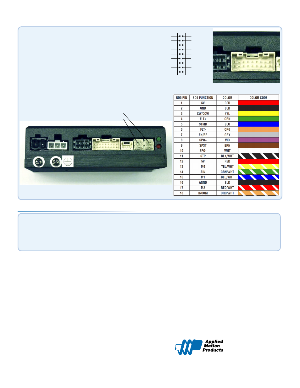
Step 3
1
3
5
7
9
11
13
15
17
2
4
6
8
10
12
14
16
18
INCOM
AGND
AIN
FLT-
SPO-
SPO+
FLT+
GND
5V
M2
M1
M0
STMD
SPST
EN/RE
CW/CCW
5V
STP
CN4
ACC/DEC
SPD
▪
Ensure that DIP switch 1 is ON and 2 is OFF (to use internal power supply
for I/O). Note, it may be necessary to remove the external cover to access
the internal DIP switches. It may also be possible to access these switches
by carefully reaching through the slots with the small screw driver that is
included.
▪
Speed and accel/decel settings are controlled by on-board
potentiometers, adjustable using the included screwdriver.
▪
Apply power to the drive.
▪
TESTING: To start the motor spinning, connect STP (pin11, black/white)
to GND (pin2) and adjust the SPD pot to the desired speed. To reverse
direction, connect CW/CCW (yellow) to GND (pin2).
ACC/DEC
SPD
Step 4
Your drive is now wired for use.
For further details on I/O and general operation please consult the BD5/10 Hardware Manual,
av