Computronic Controls Guardian User Manual
Page 4
CCL Guardian series installation and operation ci0003 issue 4 2014-05-06 p4/8
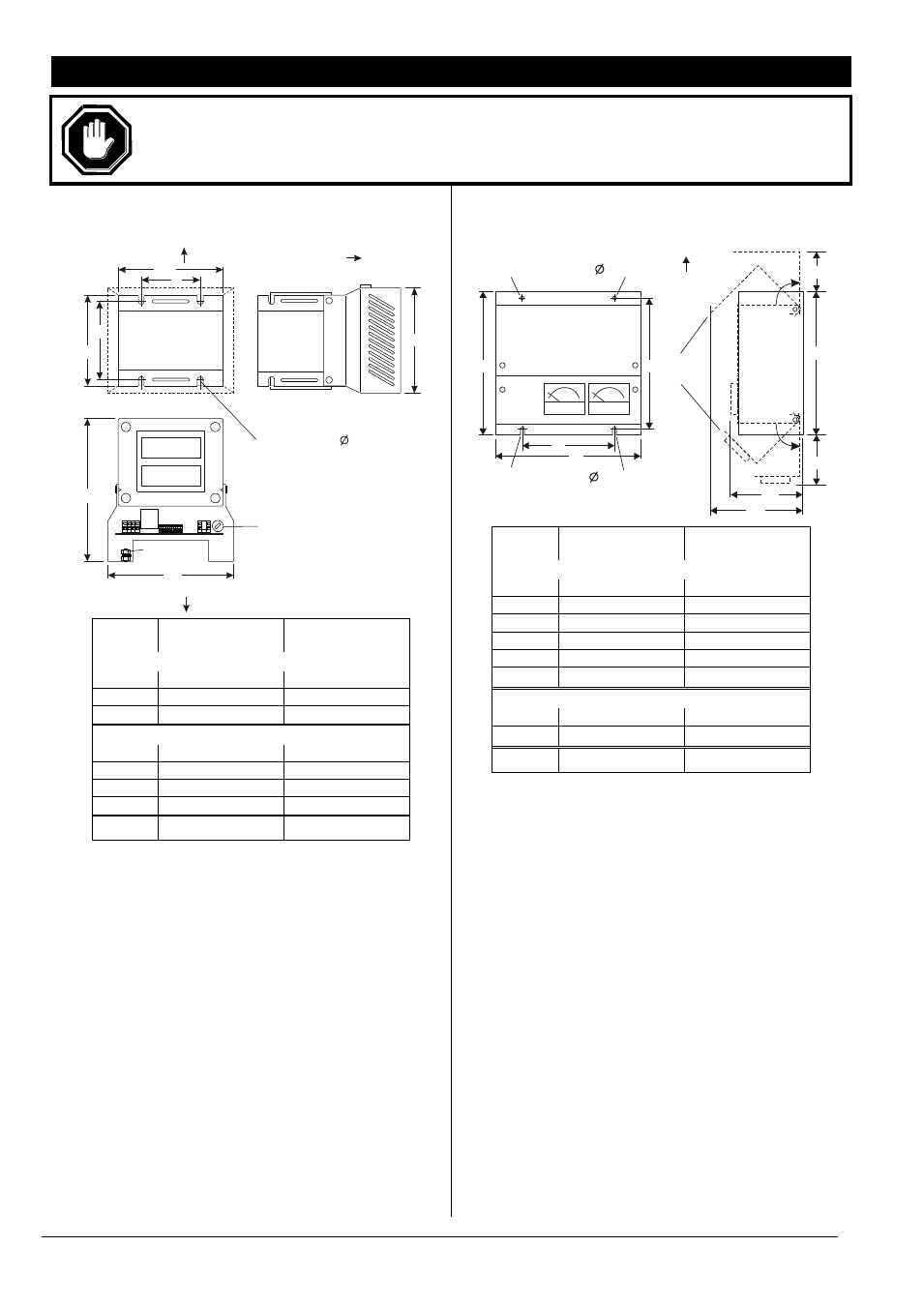
DIMENSIONS AND ASSEMBLY
CAUTION: When handling chargers, care should be taken not to place excessive weight or strain on either the
heatsink, circuit boards, transformer or connecting wires. The units should be handled by the transformer
frame (open frame models) or steel enclosure (enclosed models). Care should also be taken not to handle
static sensitive components on the circuit board.
OPEN FRAME MODELS:
G150, G300, G600
X
Y
W2
D
W1
H1
H2
TOP VIEW
AC supply
earth stud
fuse F1, AC supply
SIDE VIEW
front
front
up
BACK (FIXING PLATE) VIEW
4 x fixing slots, 6mm
G150, G300
series
G600
series
Overall:
W1
152mm / 5.98
”
152mm / 5.98
”
H1
125mm / 4.92
”
142mm / 5.59
”
D
170mm / 6.69
”
220mm
/ 8.66”
Fixing plate:
W2
125mm / 4.92
”
130mm / 5.12
”
H2
110mm / 4.33
”
130mm / 5.12
”
X
70mm / 2.76”
95mm / 3.74
”
Y
92mm / 3.62”
110mm / 4.33
”
Weight
7.0 Kg / 15.4 lb
12.5 Kg / 27.5 lb
These chargers are designed for mounting on a vertical
facia or plate inside a control panel or housing. For safe
heat dissipation, mount the product in the orientation
shown with a minimum air-gap clearance of 40mm
above/below and 25mm at sides. Consideration must
be given to ventilation for proper heat dissipation.
4 chassis slots (Ø 6mm) are provided for mounting.
Ensure that the mounting studs/bolts/nuts/screws
adequately support the charger weight, and are tightened
sufficiently to not to become loose during normal use
(e.g. due to engine/equipment vibration).
WALL MOUNTED ENCLOSURE MODELS:
EG150, EG300, EG600
2 x fixing slots, 6mm
2 x fixing holes, 6mm
up
hinged
sections
X
F
F
F
F
A
V
W
SIDE VIEW
FRONT VIEW
D1
D2
Y
H1
H1
H2
H3
EG150, EG300
series
EG600
series
Overall:
W
275mm / 10.83”
335mm / 13.19”
H1
280mm / 11.02”
310mm / 12.20”
H2
75mm / 2.95”
85mm / 3.35”
H3
90mm / 3.54”
100mm / 3.94”
D1
125mm / 4.92”
145mm / 5.71”
D2
190mm / 7.48”
210mm
/ 8.27”
Fixing holes:
X
172mm / 6.77
”
223mm / 8.78
”
Y
255mm / 10.04
”
285mm / 11.22
”
Weight
10.0 Kg / 22.0 lb
17.5 Kg / 38.5 lb
These chargers are designed for wall or frame mounting
in the orientation shown above, with enclosure air vents
uppermost. For safe heat dissipation, allow a minimum air-
gap clearance of 40mm above/below and 25mm at sides.
Adequate consideration should be given to ventilation for
proper heat dissipation.
Mounting is via the enclosure back-plate, using 2 slots
(Ø 6mm) on the back-plate lower edge and 2 holes
(Ø 6mm) on the upper edge. Ensure that the mounting
studs/bolts/nuts/screws adequately support the charger
weight, and are tightened sufficiently to not to work loose
during normal use (e.g. due to engine/equipment
vibration).
Access to the electrical connection terminals is via hinged
sections on the front facia. Remove the 4 x securing
screws (marked F above), and rotate the upper and lower
sections through 90 degrees.
Electrical cable entry is via knock-outs on either side of the
enclosure, which must be carefully removed from the
enclosure sides. A suitable cable-gland (20 mm /
0.8”
diam.) must be used to prevent damage to cables and
stop unwanted entry into inner part of charger.
Connect the charger wiring as detailed in the following
section, “Electrical connection”. When wiring is complete,
and before using the charger, re-secure the hinged
sections using the 4 fixing screws.
Phase-out
/ Discontinued
Product
Check
Availability