Assembly, Safety precautions, Mounting the bracket to the cabinet – d&b Z5091 Ci Flying bracket User Manual
Page 4: Deployment of the ci7-top
5. Assembly
5.1. Safety
precautions
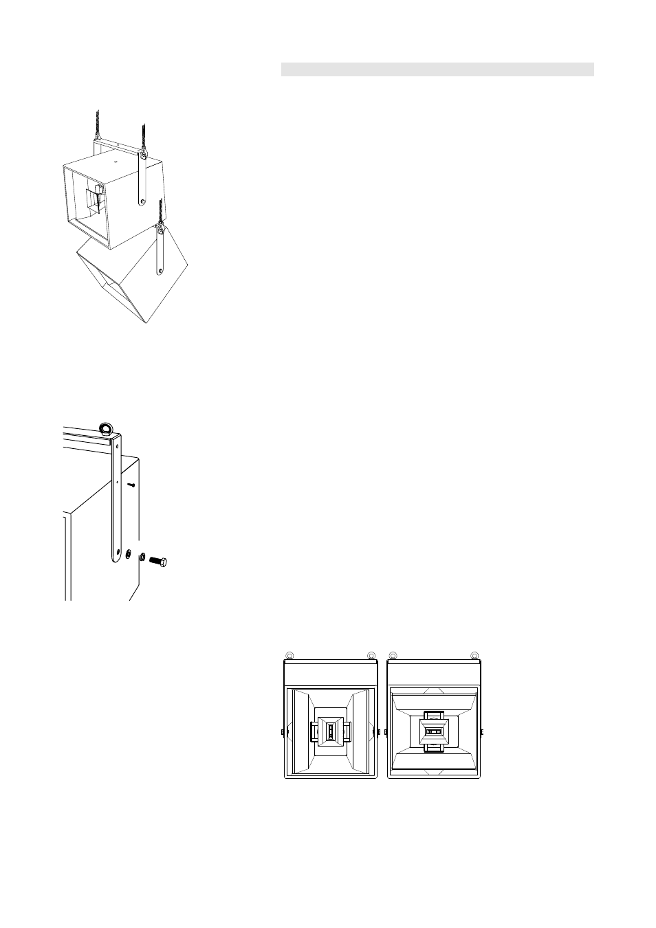
Fig. 3: Vertical array with two
Ci7-TOP. Both cabinets suspended
independently.
Installation should only be carried out by fully trained personnel. There
are certain rules for installation that must be complied with.
It is the responsibility of the person installing the assembly to ensure that
the structure being attached to is suitable for the intended use.
The Z5091 Ci Flying bracket must only be used to suspend a single d&b
Ci7-TOP, Ci7-SUB, Ci4-TOP and Ci-SUB loudspeaker cabinets as
described in this mounting instructions.
The bracket must only be used to support the cabinet from the top, i.e.
both side arms of the bracket must point vertically downward.
To set up an vertical array of e.g. two Ci7-TOP cabinets, each cabinet
with the mounting bracket assembly must be suspended from two
separate and independently rigged suspension points.
All additional rigging parts used must have a suitable load safety factor
and safety approval for their intended load.
Eye bolts or a TV spigot have to be firmly secured using M12 self locking
nuts and spring washers.
Secondary safety must always be provided when suspending
loudspeaker cabinets overhead.
5.2. Mounting the bracket to the cabinet
[2]
[2.1]
[2.2]
[3]
Fig. 4: Z5091 Ci Flying bracket assembly
The bracket is fixed to the M16 threaded inserts of the cabinet side
panels using the supplied M16x40 bolts [2], spring [2.1] and plain
washers [2.2].
The vertical angle of the cabinet can be set before fully tightening the
bracket fixing bolts.
To finally lock the cabinet in place a pair of pozidrive screws (4x20) [3]
are inserted through holes provided on each side of the bracket and
screwed into the cabinet sides.
Five 13 mm holes are provided in the bracket for fitting M12 safety eye
bolts [4] (Q9030) or a Z5018 TV spigot M12 (centre hole of the tie bar).
5.3. Deployment of the Ci7-TOP
The Ci7-TOP can be deployed for either 75° x 40° or 40° x 75°
coverage depending on which pair of M16 threaded inserts are used to
mount the Z5091 Ci Flying bracket.
a)
b)
Fig. 5: Deployment of the Ci7-TOP for either 75° x 40° (a) or 40° x 75°
(b) coverage using the Z5091 Ci Flying bracket
Z5091 Mounting instructions
(4.0EN)
Page 4 of 6