Intended use, Safety precautions, General safety – d&b Z5372 T Horizontal bracket User Manual
Page 4: Load safety information, Mounting options and coverage angles
2.
Intended use
The Z5372 T Horizontal bracket must only be used in conjunction with
d&b T10 loudspeakers as described in these mounting instructions.
Installation and setup should only be carried out by qualified and
authorized personnel observing the valid national Rules for the
Prevention of Accidents (RPA).
It is the responsibility of the person installing the assembly to ensure that
the suspension/fixing points are suitable for the intended use.
The bracket allows T10 loudspeaker cabinets to be mounted and set to
different horizontal or vertical angles. For this purpose two inner holes
9 mm (0.35") at the d&b standard spacing of 115 mm (4.5") and two
outer holes 6 mm (0.26") are provided on the tie bar of the bracket.
The bracket can be:
–
directly mounted to walls or ceilings.
–
horizontally flown and mounted to bars and trusses with a tube
diameter of up to 50 mm (2") using the following d&b
accessories:
-
Z5010, TV spigot with fixing plate
-
Z5012, Pipe clamp for TV spigot
NOTICE: Observe the maximum permitted load of the additional
rigging accessories as stated in the respective mounting
instructions.
3.
Safety precautions
General safety
Always carry out a visual and functional inspection of the bracket
before use. In case you have any doubt as to the proper functioning
and safety of the bracket, do not use it. Please also refer to section 6.
Maintenance and care on page 6.
Load safety information
The maximum permitted working load of the bracket is
11 kg (24 lb)
(according to BGV C1) which corresponds to the weight of a single T10
loudspeaker.
4.
Mounting options and coverage angles
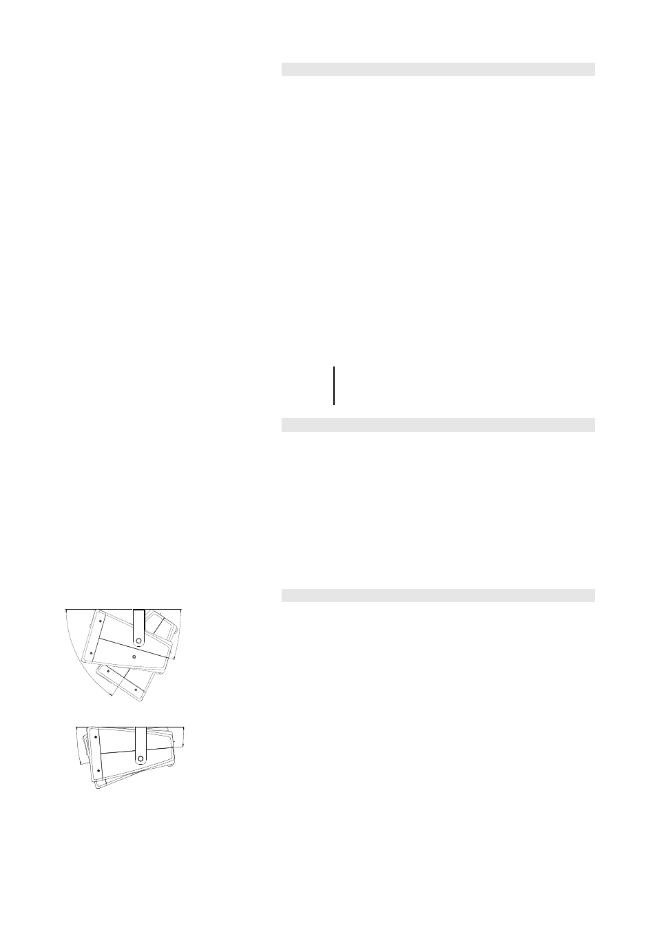
56°
16°
Fig. 3: Option 1
5°
14°
Fig. 4: Option 2
The two M10 threaded inserts at the top and bottom of the loudspeaker
cabinet are used to attach the bracket in two different ways:
Option 1 - Fig. 3:
Using the upper threaded inserts allows for a vertical alignment of the
cabinet within an angle range of 72° (+16° to –56°).
Option 2 - Fig. 4:
Using the bottom threaded inserts allows the cabinet to be mounted as
close as possible to the respective surface e.g low height ceilings within
an angle range of 9° (–5° to –14°).
Z5372 Mounting instructions
(1.0 EN)
Page 4 of 8