Dataman 570 Series User Manual
Page 9
Development kit for DATAMAN 570 series
Programmer’s Guide
0
1d
2d
3d
4d
-1d
-2d
-3d
-4d
t
Ut
1.
2.
3.
4.
5.
6.
7.
8.
9.
10.
5.
7.
1.
4.
8.
3.
2.
10.
9.
6.
5.
7.
1.
4.
8.
3.
2.
10.
9.
6.
5.
7.
1.
4.
8.
T2
T3
T1
T4
T5
T6
T7
T8
T9
T10
1
2
3
4
5
6
7
8
9
10
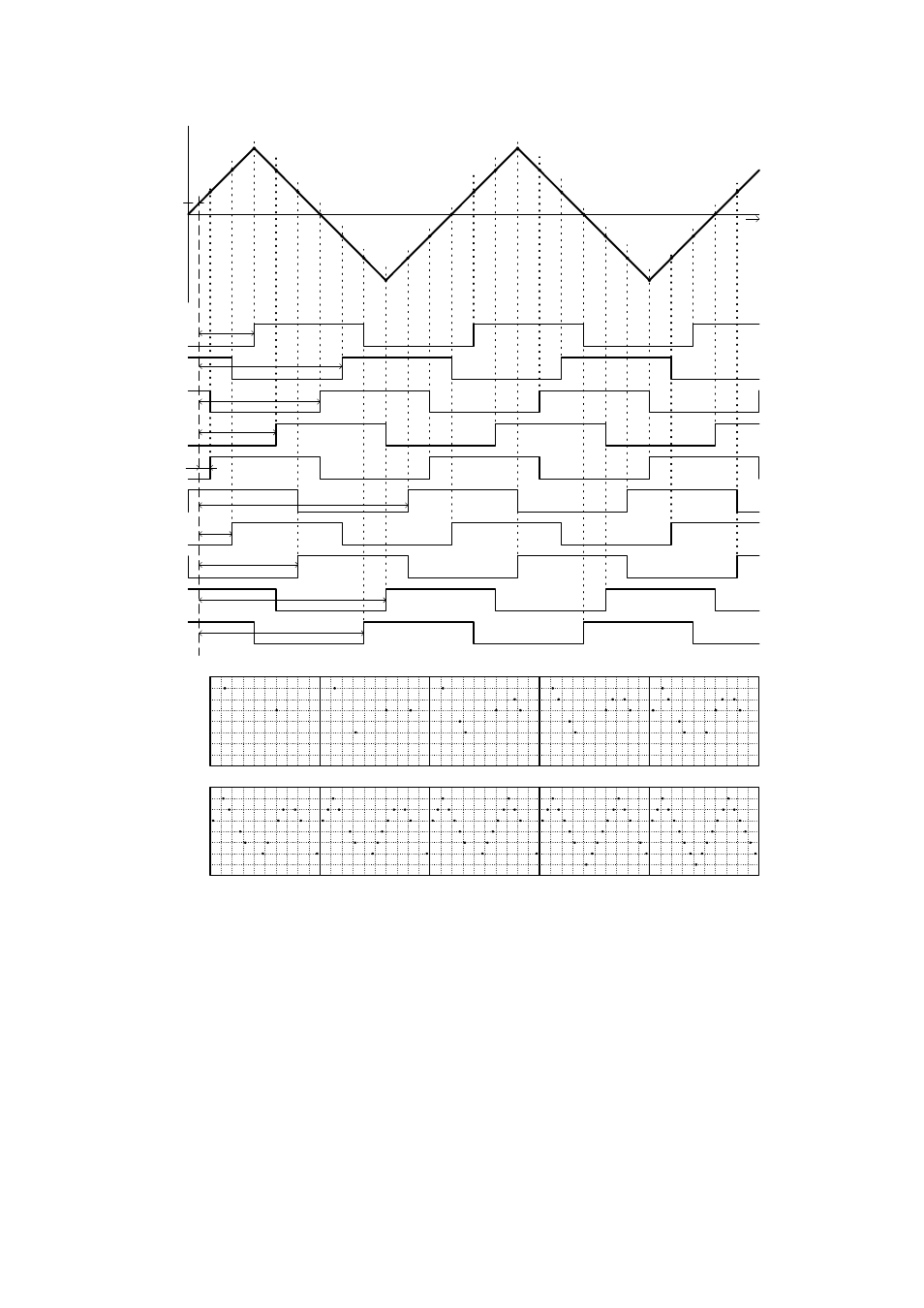
Fig. 2.5.1.1. – Random sampling principle
The trigger’s threshold is set to Ut with the rising edge of trigger input selected.
Below the sampled waveform there are shown ten sampling clocks after valid trigger
events. Because the phase of the sampling clock and the trigger event are independent
(asynchronous) in time, the time period between the trigger event and the rising edge
of the first sampling clock after the trigger event is a random value (T1 thru T10).
Using these time periods it is possible to reconstruct the measured waveform. Every
step of the reconstruction is shown at the bottom of the picture. This is the way in
which you can multiply the sampling rate of the oscilloscope.
For sampling rate multiplication by N it is necessary to perform a minimum N
subsequent measurements. In the majority of cases it is necessary to perform more
- 9 -