Menu map, Operation – ILUMINARC Ilumicode™ Addresser User Manual
Page 13
Operation
Ilumicode V 2.21 User Manual Rev. 3
9
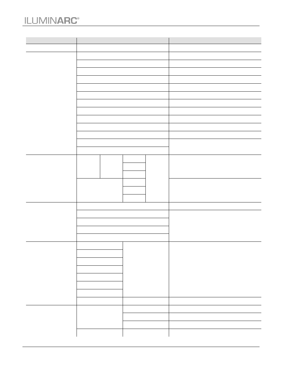
Menu Map
Main Level
Programming Levels
Description
DMX
001~512
Sets the DMX starting address
PERSON
VW
2-channel: WW,CW control
VW+D
3-channel: WW,CW control + dimmer
ARC 1
3-channel: RGB control
ARC 1 + D
4-channel: RGB control + dimmer
ARC2
4-channel: RGBW control
ARC2 + D
5-channel: RGBW control + dimmer
ARC3
5-channel: RGBWA control
ARC3 + D
6-channel: RGBWA control + dimmer
ARC FULL
7-channel: RGB control + dimmer
REMOTE
Reserved for future use
SOLID
1-channel: Dimmer
SPECIAL 1
See each product’s manual
SPECIAL 2
CALIB
WHITE
01~11
RED
000~255
Determines the white balance for the color macros
GREN
BLUE
RGB
COOL
Determines the white balance when RGBTOW is active
WARM
AMBE
DIMMER
OFF
Dimmer works in linear mode
DIM 1
Dimmer works in non-linear mode, from fast to slow
DIM 2
DIM 3
DIM 4
STATIC
RED
000~255
Configures the static color
GREN
BLUE
COOL
WARM
AMBE
SOLD
STRB
00~20
Configures strobe speed
SETTINGS
COLOR
OFF
Maximum output, unbalanced white
RGBTOW
White output is as per CALIB > RGB settings
UC
Output matches that of product’s previous versions
RESET
NO/YES
Restores factory defaults