Wiring – KLING & FREITAG K&F SWi 118E User Manual
Page 21
User’s Manual
K&F ‘SW’ Series Subwoofer Systems
KLING & FREITAG GMBH ©1998 - 2015
Version 5.1, 29.05.2015
Page 21 of 21
8. Wiring
The Speaker is equipped with two parallel-wired Speakon connectors.
Before connecting your speaker as shown in chapter 9 be sure to switch off all connect-
ed appliances and turn down all level controls.
− We recommend the use of high-quality speaker cables provided by KLING & FREITAG.
− For connections from the mixing console to the power amplifier inputs, please use 2-
pin shielded microphone cable with high-quality connectors.
− Avoid ground loops (see chapter 8.2 Avoiding Ground Loops)
− Please pay attention to the respective pin diagrams in this manual!
− Make sure that the +/- polarity between speaker and amplifier is correct. When simul-
taneously using power amplifiers from different manufacturers, be sure to use the
correct specific pin configuration. It may be necessary to modify the pin configuration
on the power amplifiers or on the connectors leading to them.
− To avoid loss of power, the cables should have a minimum wire gauge of 2.5 mm² -
more for longer cabled distances. A minimum wire gauge can be easily calculated
with the following formula:
If several loudspeakers are to be connected, the signal can be linked through from one
loudspeaker to the next. Please make sure that the total impedance of the loudspeakers
R(Ω) is not lower than the minimal impedance indicated on the power amplifier.
1/R
1
+ 1/R
2
+ 1/R
3
+ ... = 1/R
total
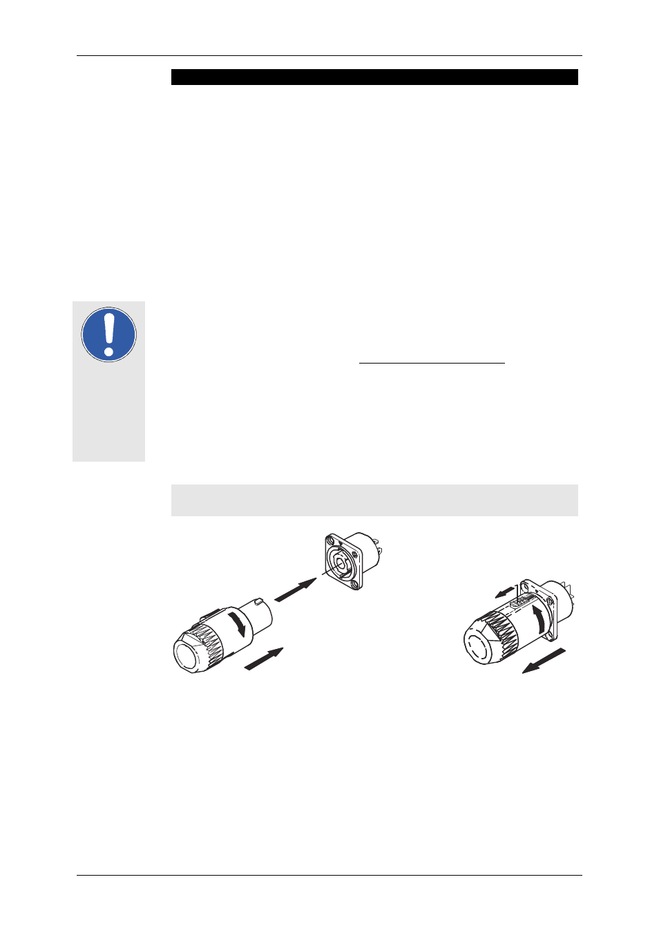
8.1 Connecting the Speakon Connectors to the Connecting Ter-
minal
2.
1.
3.
1.
2.
Important
Minimum Wire Gauge (mm²) =
Required Cable Length (m)
2 x Speaker's Impedance (Ω)