Pci 33 slot – NEXCOM NEX 604 User Manual
Page 40
Copyright © 2012 NEXCOM International Co., Ltd. All Rights Reserved.
25
NEX 604 User Manual
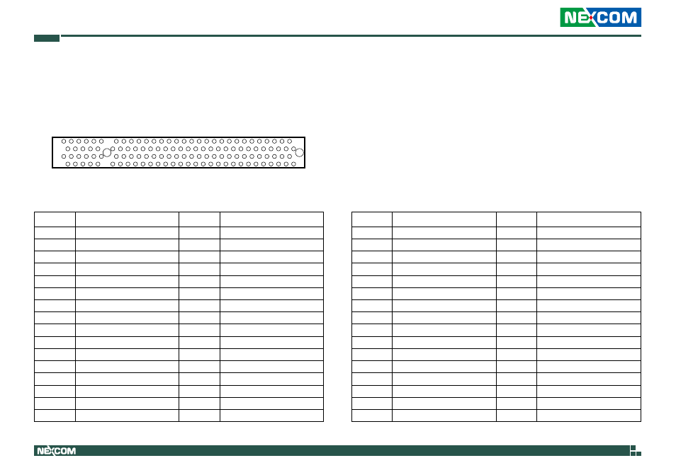
Chapter 2: Jumpers and Connectors
B62
A62
B1
A1
Pin
Definition
Pin
Definition
A1
Pull down 5.6K to GND
A2
+12V
A3
Pull high 1K to +5V
A4
Pull high 1K to +5V
A5
+5V
A6
Interrupt A#
A7
Interrupt C#
A8
+5V
A9
CLKRUN#
A10
+5V
A11
GNT#2
A12
GND
A13
GND
A14
3.3VAUX
A15
Reset#
A16
+5V
A17
GNT#1
A18
GND
A19
PME#
A20
Address and Data 30
A21
+3.3V
A22
Address and Data 28
A23
Address and Data 26
A24
GND
A25
Address and Data 24
A26
IDSEL
A27
+3.3V
A28
Address and Data 22
A29
Address and Data 20
A30
GND
A31
Address and Data 18
A32
Address and Data 16
PCI 33 Slot
Connector location: CN1
Pin
Definition
Pin
Definition
B1
-12V
B2
Pull down 5.6K to GND
B3
GND
B4
NC
B5
+5V
B6
+5V
B7
Interrupt B#
B8
Interrupt D#
B9
Connect 10nf to Ground
B10
REQ#2
B11
Connect 10nf to Ground
B12
GND
B13
GND
B14
Clock2
B15
GND
B16
Clock1
B17
GND
B18
REQ#1
B19
+5V
B20
Address and Data 31
B21
Address and Data 29
B22
GND
B23
Address and Data 27
B24
Address and Data 25
B25
+3.3V
B26
CBE #3
B27
Address and Data 23
B28
GND
B29
Address and Data 21
B30
Address and Data 19
B31
+3.3V
B32
Address and Data 17