Appendix a: gpi/o programming guide 26, I/o address function, Appendix a: gpi/o programming guide – NEXCOM nROK 500 User Manual
Page 39
Advertising
26
Appendix A: GPI/O Programming Guide
Copyright © 2012 NEXCOM International Co., Ltd. All rights reserved
nROK 500 User Manual
Appendix A: GPI/O Programming Guide
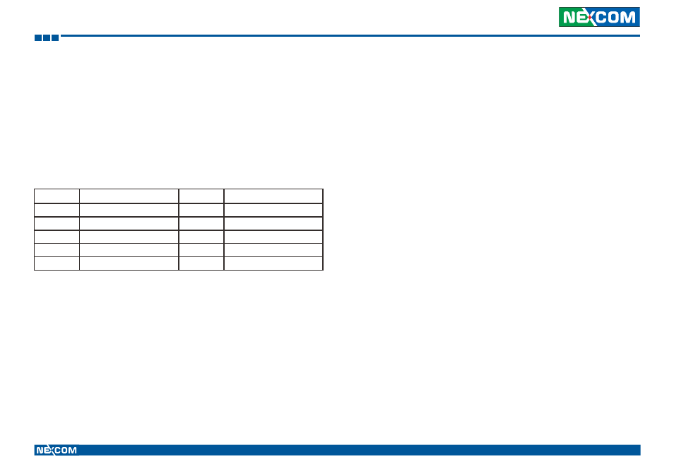
I/O Address Function
Pin
Definition
Pin
Definition
1
+5V
2
GND
3
GPIO20(Pin84)Out0
4
GPIO24(Pin36)In0
5
GPIO21(Pin70)Out1
6
GPIO25(Pin34)In1
7
GPIO22(Pin66)Out2
8
GPIO26(Pin33)In2
9
GPIO23(Pin48)Out3
10
GPIO27(Pin32)In3
Digital I/O (Digital Input/Output) pins are provided for custom system design.
This appendix provides definitions and its default setting for the Digital I/O
pins in the nROK 500. The pin definition is shown in the following table:
IO base address : 800h
Bit0 : GPO20
Bit1 : GPO21
Bit2 : GPO22
Bit3 : GPO23
Bit4 : GPI 24
Bit5 : GPI 25
Bit6 : GPI 26
Bit7 : GPI 27
1. Read/Write GPIO data by I/O port 801h
Advertising