Cable connections & setup procedures, Ystem cable connections, 4) cable connections & setup procedures – OT Systems ET1100C series User Manual
Page 7
ET1100C Series Installation & Operation Manual
7
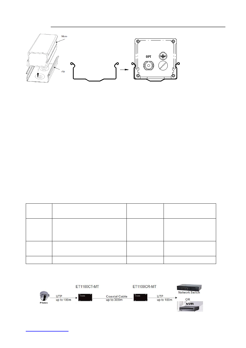
(a) Installation (b) Side view of the clip
(c) Side view of the Micro unit pushed into the clip
Fig. 3.3 Micro unit installation on the clip
d)
Connect all the signal inputs and outputs at the back of the unit with appropriate cables:
i)
Coaxial Cable
ii)
UTP cable with RJ45
e)
Once the unit is powered up, check that the red POWER LED on the unit is lit. If not, check
the power supply cable connections between the unit and the power supply socket.
f)
With all the signals available at the input and output ports, check the status of LEDs located
on the unit. With correct status of each LED, installation is now completed [for LEDs status, see
Operational Guides
on this manual’s section (5)].
(4) Cable Connections & Setup Procedures
4.1 System cable connections
Signal
Type
Cable Type
Connector
For details, please
refer to
Ethernet
Twisted-pair Cable
10BASE-T: 4-pair UTP/STP Cat3, 4, 5
100BASE-TX: 4-pair UTP/STP Cat 5
RJ45 Connector
Section 4.2.1
Line
Coaxial cable (RG6, RG58 or RG59)
BNC (Female)
75 Ohm
Section 4.2.2
12VDC
Power cord
DC Jack
Section 5
Wiring Diagram
Fig 4.1 Ethernet Extender connection diagram