Metal box controller, Wiring diagram for zone(s) (outputs) – Pinnacle Systems STTS User Manual
Page 21
15
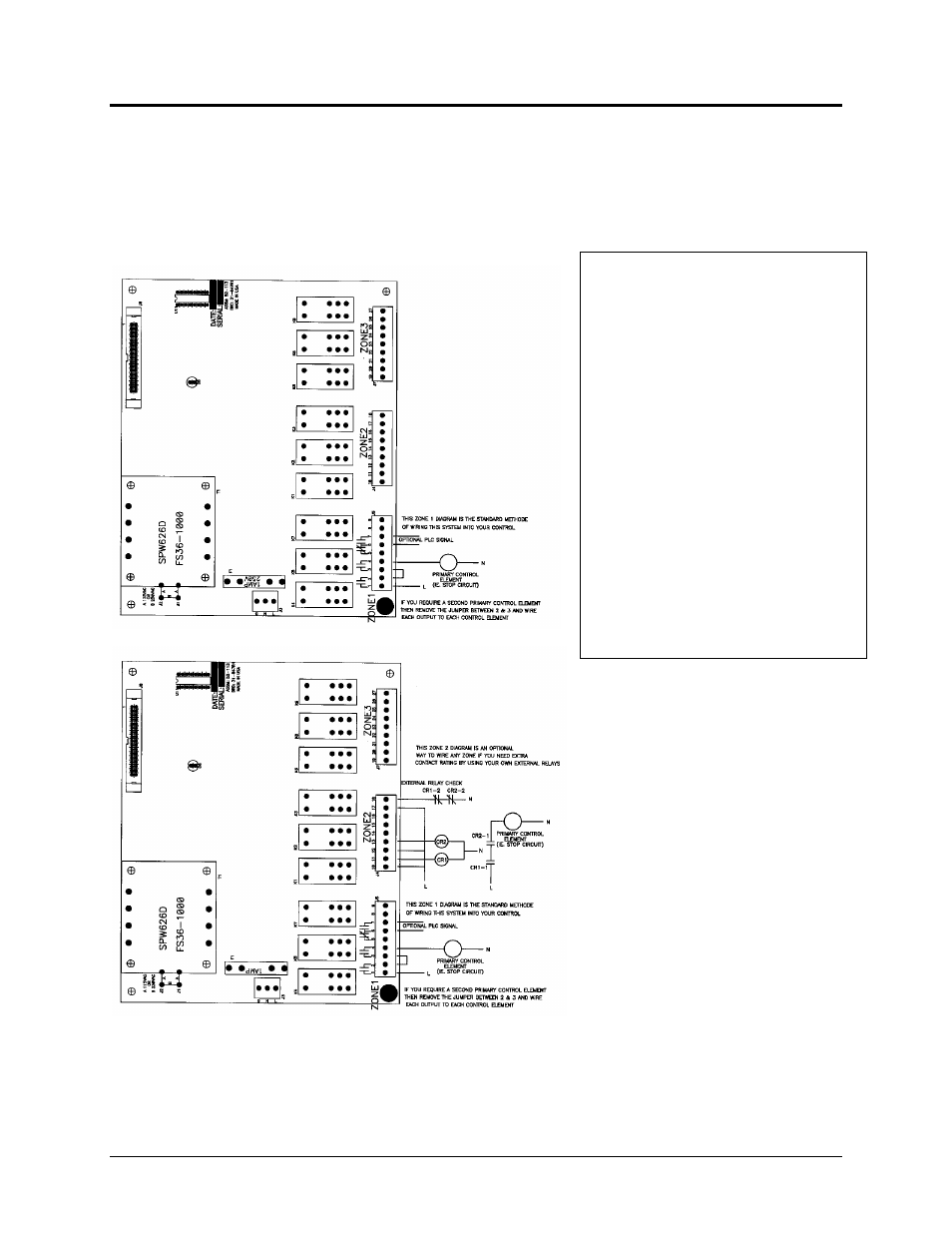
WIRING DIAGRAM FOR ZONE(S) (OUTPUTS)
Metal Box Controller
The following examples show two ways to wire a zone: Zone #1 is wired the standard method; Zone #2
is wired for use with external relays. Either of these methods can be applied to any zone.
NOTE: If you use external relays, you must use them on all available zones. You cannot have
external relays on one zone and not on the other zone.
NOTE: If you require 24VDC for power, the transformer SPW626D will be replaced with two chokes.
This modification cannot be performed in the field on the board itself, it must be done at the factory. All
“CE” marked products for the European Community must be 24VDC input power.
Knock out two holes in bottom section of
metal box housing for input power wiring
and alarm zone wiring; minimum hole size
of ½" (13mm). Care should be exercised
in protection of the conductors from
abrasion where they enter the controller
box, with conduit it is accomplished by
bushings or other approved devices. With
NM cable, the outer covering of the cable
should protrude from the clamp to provide
this protection. With armored cable, fiber
bushings are to be inserted between the
conductors and the armor to prevent any
abrasion. All fittings and connectors shall
maintain a NEMA 12 (IP 54) rating at a
minimum.
A. Openings to be closed-where
conductors enter any openings, they shall
be properly closed.
B. When conduit or fittings are used
with open wiring, proper bushings
shall be used.