Description of connectors, Led indicators – Televes T.0X Encoder TWIN HDMI/Composite CVBS - COFDM/QAM User Manual
Page 3
5
6
1
2
3
4
2
3
5
6
7
8
1
11
12
10
4
9
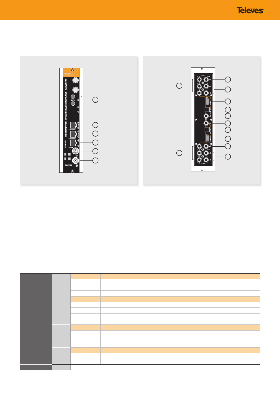
Description of connectors
Front view
LED indicators
Rear view
1.- Power connectors
2.- Ethernet connector
3.- Ethernet connector
4.- Programmer connector
5.- RF loop through input
6.- RF output
1.- YPbPr component input. Channel 1
2.- CVBS input. Channel 1
3.- Analog (L/R) audio input. Channel 1
4.- HDMI input. Channel 1
5.- SPDIF digital optical audio input. Channel 1
6.- SPDIF digital coaxial audio input. Channel 1
7.- SPDIF digital coaxial audio input. Channel 2
8.- SPDIF digital optical audio input. Channel 2
9.- HDMI input. Channel 2
10.- YPbPr component input. Channel 2
11.- CVBS input. Channel 2
12.- Analog (L/R) audio input. Channel 2
Front LED alarms
TEMP
Color
Internal temp
Comment
Solid green
Normal
Safe
Slow blink orange
High
Warning
Fast blink red
Very High
Danger
CH1 – CH2
Color
Channel status
Comment
Off
Disabled
Channel disabled.
Solid green
Lock
Input locked and unit encoding audio/video.
Solid red
Unlock
Input unlocked and unit not encoding audio/video.
Blinking red
Boot
Unit starting up.
OUTPUT
Color
Output mode
Comment
Solid green
Normal
Output RF channel is ON, broadcasting audio/video (normal mode).
Slow blinking green
Carrier wave, null, or muted
Output RF channel is OFF or in an alternate signal mode.
Solid orange/red
Normal
Config bitrate doesn´t fit in output
LOOP
Color
Output loop status
Comment
Solid green
ON
Output loop-through enabled. Units may be daisy-chained using the internal combiner.
Off
OFF
Output loop-through disabled. Units must be combined using an external combiner.
Back LED indicators
A/V inputs
Indicate the currently selected audio and video inputs and where the input signals should be connected.