Standard installation, Floor protection, Clearances to combustibles – United States Stove Company 4840 User Manual
Page 5
Ussc
5
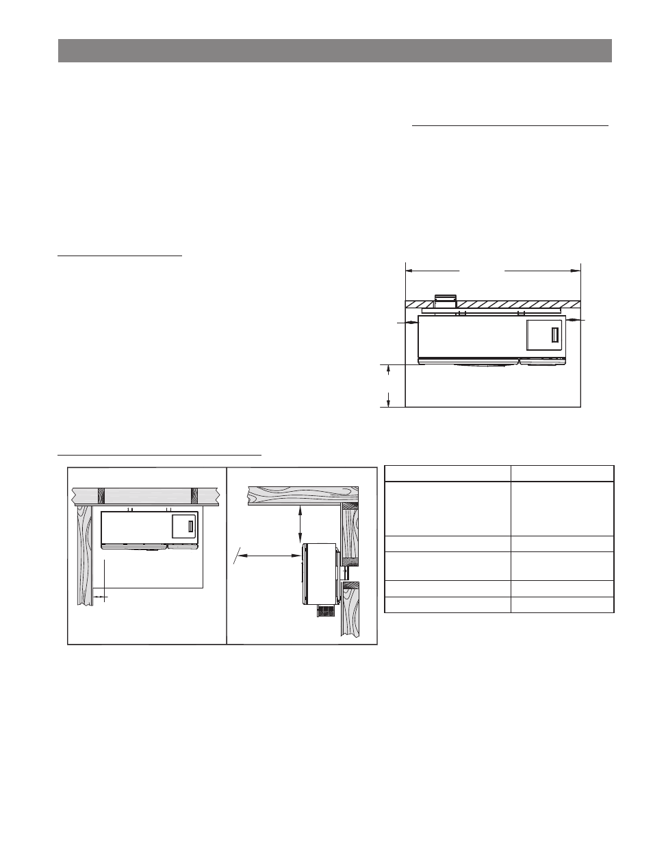
FLOOR PROTECTION
This heater must have a non-combustible floor protector (ember
protection) installed beneath it if the fl oor is of combustible material.
If a fl oor pad is used, it should be UL listed or equal. The fl oor pad or
non-combustible surface should be large enough to extend a minimum of
6-inches [152mm] in front and 2-inches [51mm] on each side of the heater.
Canadian Installations require a minimum of 450 mm [18”] beyond the
front of the unit and 200mm [8”] beyond each side of the unit
A Floor Protector of 1/4 inch thick is recommended for this installation
CLEARANCES TO COMBUSTIBLES
Combustible
Clearance
Floor (Allow for brace)
8 inches [203mm]
Vent must meat
minimum ground
clearances
Left / Right
6 inches [152mm]
Ceiling (Allow for
fuel loading)
18 inches [457mm]
Mantle / Sill
11 inches [279mm]
Front
60 inches [1.5M]
STANDARD INSTALLATION
6
[152]
39.
2 [51]
87 [91012]
2 [51]
Floor Protector
6” [152mm]
18”
[457mm]
60”
[1.5M]
Floor Protector
Back Wall
4
J
E
F
8
B
M
M
#
B
D
L
8
B
M
M
Ceiling
Read this entire manual before you install and use your pellet heater. Failure to follow instructions may result in property damage,
bodily injury, or even death!
Before installing your heater, you must perform an initial burn in an OUTSIDE environment. Follow the Start-Up Procedure in
the Operation section of this manual.
Your pellet heater may be installed to code in either a conventional or mobile home (see SPECIAL MOBILE HOME REQUIREMENTS).
It is recommended that only a authorized technician install your heater, preferably a National Fireplace Institute (NFI) certifi ed
specialist. This heater must be installed on an exterior wall to allow exhaust venting to meet the minimum required clearances. Once
the desired location is selected, and before cutting a hole, check the outside of the structure for anything obstructing clearances to
the exhaust vent. Also clear away leaves, shrubs/bushes, or trees that may be around the exhaust outlet.
Required Tools for installation:
General Installation Notes
• Do not install heater where the exhaust will terminate in a window well or any opening below ground level.
• Special precautions may be required to prevent snow build-up within 12 inches of the air intake.
• Clearances around heater must provide adequate room for service, cleaning, and air circulation.
• Residential Garage Installation: The heater shall be located or protected so it is not subject to damage by a moving
vehicle. Use care when selecting a good location within the garage. DO NOT locate the heater where the discharge air
will be directed onto a nearby parked vehicle. DO NOT store containers of paint, gasoline, or other fl ammable liquids in
the same area as the heater, inside or outside the home or structure.
1. Venting
Kit
2. Power
Drill
3. 7/32” drill bit to drill pilot holes
4. Wrench / Socket.
5. Hammer
6. Knife
7. Pen
8. Noncombustible
fl oor protector