Wall installation, Step: 1 mount the wall plate – United States Stove Company 4840 User Manual
Page 6
6
Ussc
• Select a wall to the exterior of the building. This wall should have the required clearance to combustibles inside and out
as mentioned in this manual. Make certain that electrical wires, conduit, water or gas pipes do not pass through the area
you have selected.
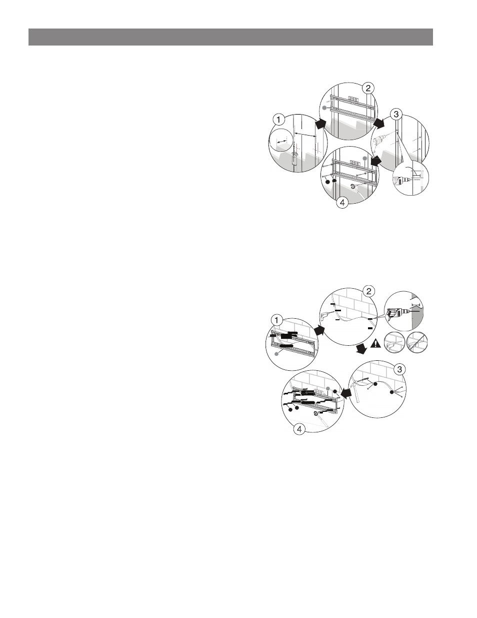
STEP: 1 MOUNT THE WALL PLATE
Note: Any material covering the wall (such as sheetrock) must not exceed
5/8” 16 mm).
Option 1: Mounting on a wood-stud wall
1. Locate the studs in exterior wall. Verify the center of the stud with an
edge-to-edge stud fi nder. Mark center point at predetermined height.
2. At the wall height you determined in the previous step, place a small
nail thru center triangle hole of bracket and align the wall mount
against the wall. Level bracket and verify that pilot holes are centered
on studs. Use a pencil to mark the screw hole locations, and intake/
exhaust thru hole then remove the wall plate.
3. Drill pilot holes to a depth of 3” (75 mm) using a 7/32” (5.5 mm)
diameter drill bit.
4. Carefully cut intake/exhaust thru hole in exterior wall thru to the
outside. (SEE VENT CLEARANCES SECTION TO INSURE
PROPER INSTALLATION)
5. Realign the wall mount with the pilot holes and intake/exhaust thru hole. Insert 1/4” x 2” lag bolts with washers, and tighten the
lag bolts until the washers are pulled fi rmly against the wall mount and the wall mount is pulled fi rmly against the exterior wall.
WARNING: AVOID POTENTIAL INJURIES OR PROPERTY DAMAGE! DO NOT OVER-
TIGHTEN THE LAG BOLTS.
Option 2: Mounting on a solid concrete or concrete block wall
1. Level the wall plate and mark the hole locations.
2. At the wall height you determined in the previous step, place a small
nail thru center triangle hole of bracket and align the wall mount
against the wall. Level bracket and verify that pilot holes are not
located in the mortar of the cinder blocks. Use a pencil to mark the pilot
hole locations, and intake/exhaust thru hole then remove the wall plate.
3. Drill pilot holes to a depth of 3” (75 mm) using a 1/2 in. (12.7 mm)
diameter masonry drill bit.
4. Carefully cut intake/exhaust thru hole in exterior wall thru to the
outside. (SEE VENT CLEARANCES SECTION TO INSURE
PROPER INSTALLATION)
5. Insert 1/4” concrete wall anchors into the pilot holes and make sure
that the anchors are seated fl ush with the concrete surface.
6. Align the wall plate with the anchors. Place washers over the screw
holes in the wall plate, insert 1/4” x 2” lag bolts through the washers,
and then tighten the lag bolts until the washers are pulled fi rmly against
the wall plate and the wall mount is pulled fi rmly against the exterior wall.
STEP: 2 MOUNTING THE HEATING UNIT TO THE WALL PLATE
Note: The Heating Unit is heavy. You will need assistance with this step.
1. After mounting Wall Plate to wall. Cut hole
2. Align intake/exhaust with hole in wall and carefully insert heating unit. Tilt top towards the wall and lower the Heating Unit
onto the wall plate making sure that the hooks on the top of the left and right brackets slide over the top of the wall plate. Allow
the Heating Unit to pivot parallel to the wall plate and lift to allow lower hooks to engage on the bottom of the Wall Mount.
3. Insert locking brackets into the lower slots of Heating Unit back mounting brackets. Tighten ¼-20 hex head bolts to lock
Heating unit onto Wall Plate.
5/8”
[16mm]
16”
[406mm]
3”
[75mm]
WALL INSTALLATION