Vectronics SWR-584C User Manual
Page 15
SWR-584C Instruction Manual
HF/VHF/220MHz SWR Analyzer
15
minimal compared to forward power. A smaller number (-9.5 dB) equates to higher SWR (~
2:1) because the difference between forward and reflected power is less. Reflection Coefficient
(ρ) expresses the voltage relationship between the reflected wave and the forward wave on a
scale of 0 to 1.0. A Reflection Coefficient of 0.2 is approximately equal to 1.5:1.
To access and view measured data for Return Loss (RL) and Reflection Coefficient (ρ):
[ ] Turn on the analyzer and allow it to boot to the basic system default mode (R&X).
[ ] Connect the DUT to the Antenna jack
[ ] Press Mode and Gate together until Advanced appears on-screen, then release.
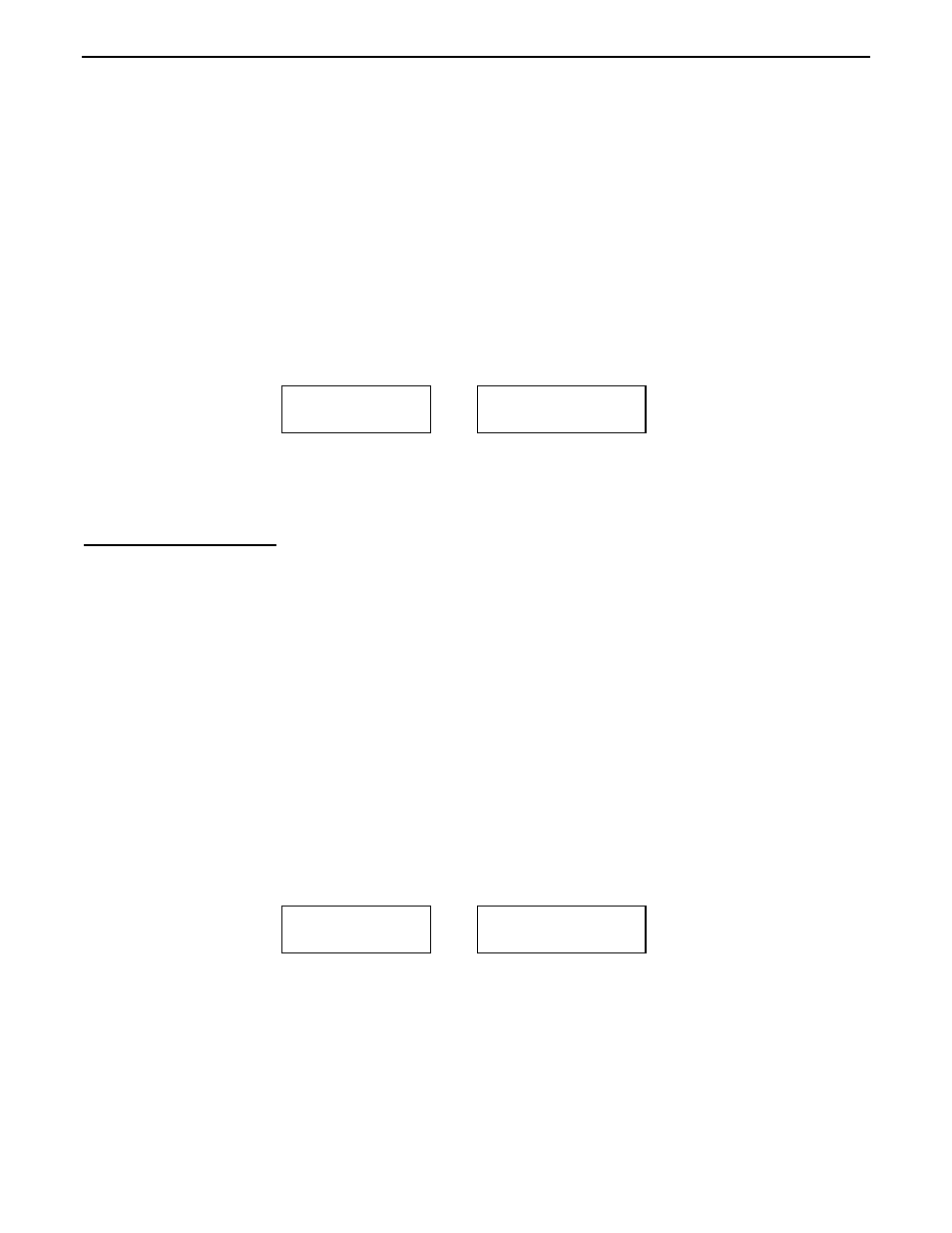
[ ] Press Mode once to access Return Loss & Reflection Coeff.
[ ] Wait for the working screen.
[ ] Adjust the Frequency switches and Tune control to the desired test frequency (MHz).
[ ] Read numerical Return Loss (RL), (SWR), Reflection Coefficient (ρ) on the display:
[ ] Read Impedance and SWR on the analog meters.
5.5 Distance To Fault: In DTF mode, you can measure the physical length of a random run of
cable or find the distance to a fault in a transmission line. To do it, you'll first measures the
electrical distance
to the abnormality (or the cable end), then multiply it times Velocity Factor to
get a physical distance in feet. At the far end of the cable, open and shorted terminations yield
the best accuracy (resistive or reactive terminations can skew results or fail to test). You may
also test balanced line using this method, but it requires a special procedure to keep the line in
balance and isolated from ground (see below). Coax can be tested in any configuration.
Balanced Line: To avoid proximity errors, twin-lead, window line, ladder line, and open-wire
feeders needs to be suspended in a straight line in the air and a few feet away from earth or
other conductors. The analyzer must also be isolated from proximity to ground by running on
internal battery power with only the feedline under test attached. One leg connects to the
Antenna jack center pin and the other goes to the analyzer ground stud or connector flange.
To measure fault distance:
[ ] Connect the DUT to the Antenna jack
[ ] Enter Advanced Mode
[ ] Press Mode twice to access Distance To Fault. Wait for the working screen:
The top line shows Frequency and a blinking "1st" prompt. The lower line shows Reactance.
To find electrical length, you'll find and enter two consecutive frequencies where (X=0).
[ ] Using the VFO, search for the lowest frequency you can find where the Impedance meter
shows a sharp null and the display shows X=0 (or as close to 0 as possible).
[ ] Press Gate to enter that frequency. The display will switch to the 2nd prompt
Return Loss &
Reflection Coeff
14.150 1.3
RL=18 ρ=.13 SWR
Distance to Fault
in feet
5.0000MHz
1st
DTF X=23