Vectronics SWR-584B User Manual
Page 14
SWR-584B Instruction Manual
HF/VHF SWR Analyzer
14
5.0 ADVANCED
OPERATION
WARNING: NEVER APPLY RF OR ANY OTHER EXTERNAL VOLTAGES TO THE ANTENNA
PORT OF THIS UNIT. THIS UNIT USES ZERO BIAS DETECTOR DIODES
THAT ARE EASILY DAMAGED BY EXTERNAL VOLTAGES OVER A FEW
VOLTS.
The advanced mode is reached by pressing and holding the GATE and MODE buttons together for several
seconds. Upon release of the buttons, and “ADVANCED” message will appear. The following modes are
available from the ADVANCED menus:
Impedance......................................................................... SWR, impedance magnitude, phase angle of impedance
Return Loss and Reflection Coefficient ........................... SWR, return loss, impedance, reflection coefficient
Distance to fault................................................................ SWR, impedance, and distance to fault
Resonance ......................................................................... SWR, resistance and reactance
Transmit efficiency........................................................... SWR, impedance and forward power as a percentage of
apparent
power
5.1 Forward
In the ADVANCED mode, the SWR-584B measures distance to fault, impedance, reactance, resistance, and
standing wave ratio (SWR).
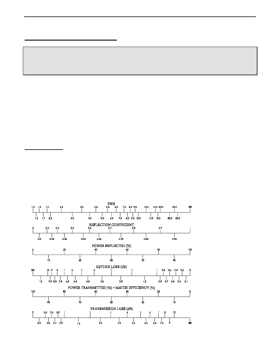
It also measures and displays other terms used to describe SWR. These esoteric SWR descriptions include return
loss, reflection coefficient, and transmitted power as a percentage of apparent power in the system. Some of
these terms are misleading because their name does not necessarily describe what really happen in a system. We
strongly recommend persons unfamiliar with information supplied in special modes avoid using them.