Vectronics VEC-1862 User Manual
Page 4
VEC-1862 Instruction Manual
Six-meter Yagi Antenna
4
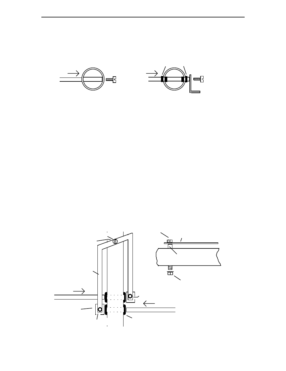
[ ] Find two (2) 59-1/4" reflector element sections and repeat the same mounting
procedure at the back end of the antenna.
Element
#10 screw
Boom
Boom
Element
"L" Bracket
#10 Screw
Insulating Grommet
Driven Element Mounting Detail
Director, Reflector Mounting Detail
[ ] Find four (4) black polyethylene insulating grommets and snap one into each driven-
element mounting hole (do not confuse these holes with the U-bolt mounting holes).
[ ] Locate the two remaining element sections (54-1/2" each) and slip the tapped end of
each through the driven-element insulating grommets.
[ ] Using 10-32 screws, install a "L" bracket on each driven element section as shown in
the construction detail. Apply Locktite to the screws and secure firmly in place,
using pliers to gently grip the element.
[ ] Locate the aluminum hairpin inductor and install as shown below, using the 6-32 x 1
3/4" screw, the 5/16" x 1/4" OD spacer, and the 6-32 Kep-nut. Note that the end
mounting holes on the hairpin should align with the driven element "L" brackets.
Hairpin Inductor
Element
#6-32 Mounting Screw
"L" Bracket
Boom
Insulating Grommet
#8 x 1/2" SM Screw
5/16" spacer
Hairpin Mounting Detail
Boom
Hairpin
5/16" Spacer
Element
#6-32 Mounting Screw
#6-32 x 1 3/4" Screw
#6-32 Kep-nut