Vectronics VEC-896 User Manual
Page 5
VEC-896 Vertical Antenna
Instructions
5
1. Prepare a temporary ground-level mounting mast that will permit easy initial testing and
adjustment. Set up saw horses or any other stable support (plastic trash cans or folding
tables, etc.) near the mast.
2a. Sort out the parts you have unpacked into groups of similar parts. Be sure all the parts are
available.
3. After examining the antenna parts, gather the tools needed for basic assembly. At the
minimum these consist of:
#1 Long Phillips screwdriver for capacitance spoke screws
#2 Phillips screwdriver for other 6-32 screws
1/4" standard screwdriver or a 5/16" nut driver for hose clamps.
3/8" wrench for 6 and 2 meter stub nuts
Two 7/16" open end wrenches or one wrench and one nut driver for "U" BOLTS and
center insulator bolts.
Wire cutters for trimming capacitance spokes.
Safety glasses.
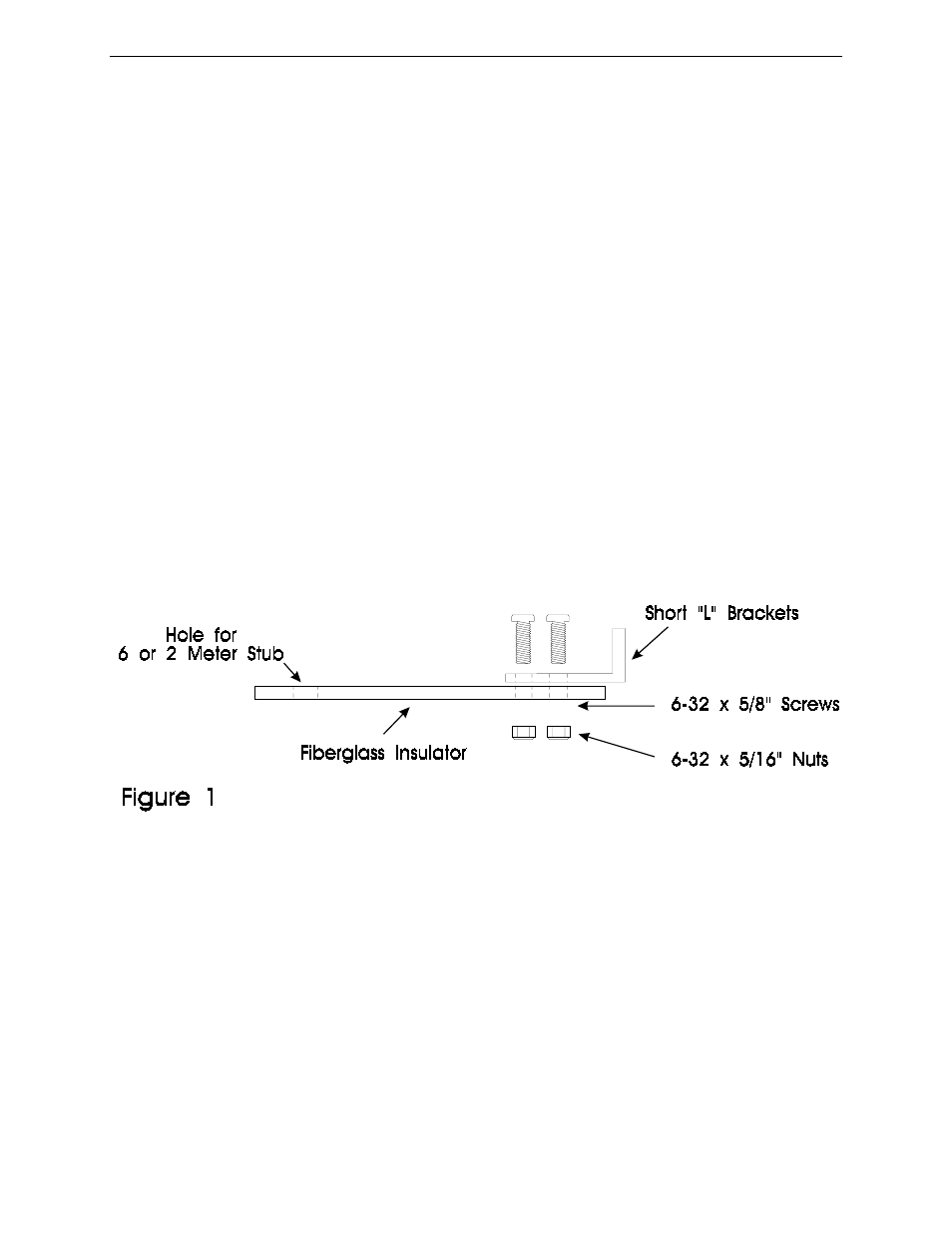
4. Assemble the four small "L" brackets to the 4 long fiberglass insulators with the 6-32 x
1/2" screws and the 6-32 x 5/16" nuts as shown in Figure 1.
5. Bolt the top balun hole loosely to the top hole in the base mounting assembly with a 1/4-
20 x 7/16" nut and the 1/4" x 7/16" head bolts. Use the hollow white nylon spacers to
separate the balun from the mounting bracket. Finger tighten only. See Figure 2.
6. Bolt the bottom balun hole to the bottom hole in the base mounting assembly as in Step 5.
7. Tighten the balun bolts with a 7/16" wrench.
8. Bolt the coax connector assembly to the base mounting assembly with four 6-32 x 5/8"
screws and 6-32 nuts. See Figure 2.