Vectronics VEC-101K User Manual
Page 11
VEC-101K Owner's Manual
Shortwave Converter Kit
9
Phase 1: Molded Chokes
Important Note: only the first three color bands are specified in the following
directions. The fourth band is for tolerance and may be disregarded.
Locate the 180-uH molded choke (brown-gray-brown).
! ! 1. Install and solder the 180-uH choke (brown-gray-brown) at location
L5 on the PC board.
Important Note: You need to determine the two SW bands the VEC101 will
cover. Chokes L1 and L3 are used for the lowest frequency band, chokes L2
and L4 are selected for the higher frequency band. Band selection is via switch
SW2. Push button is in for lowest frequency band, push button is out for
highest frequency band.
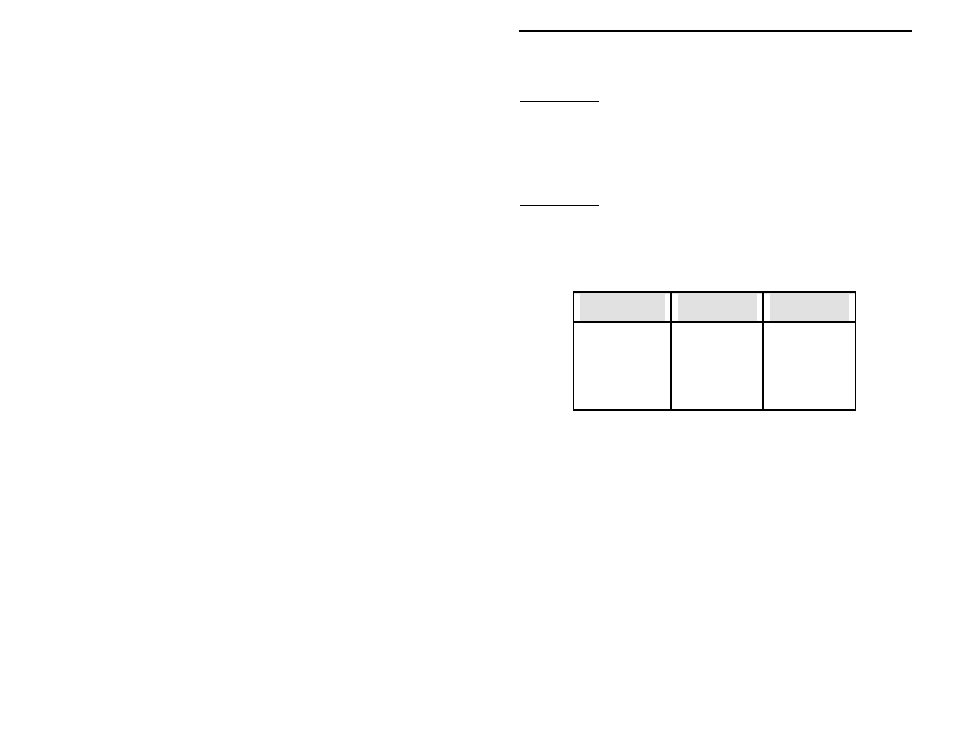
The choke values for the following steps are determined by the following:
Desired
coverage
L1, L3
low range
L2, L4
high range
3.0 to 5.8 MHz
33 uH, 33 uH
use low range
5.0 to 9.0 MHz
10 uH, 10 uH
10 uH, 10 uH
8.0 to 14.5 MHz
3.9 uH, 3.9 uH
3.9 uH, 3.9 uH
13.9 to 23 MHz
use high range
1.2 uH, 1.2 uH
Table 1
Example:
Your favorite SW bands are 31 Meters and 49 Meters. 49 Meters is from 5.95
MHz to 6.20 MHz. 31 Meters spans from 9.50 MHz to 9.90 MHz.
According to the data in Table 1, 10-uH chokes should be used for the 49-Meter
band (5.95 to 6.20 MHz). Because this is the lowest frequency band of the two
we are selecting, the 10-uH chokes will be used at locations L1 and L3.
Referring to Table 1 again shows for 30 Meters (9.5 to 9.9 MHz) coverage 3.9-
uH chokes should be used at locations L2 and L4.
! ! 2. Determine the two shortwave frequency ranges or SW bands you wish
to monitor. Refer to Table 1 for the proper choke values. Note: Some
bands, such as 16 and 13 Meters, share the same choke value. Only
one of those two bands may be covered.