Parts list – Vectronics VEC-1292K User Manual
Page 4
VEC-1292K Owner’s Manual
Stereo Transmitter Kit
4
Reading Capacitors: Unlike resistors, capacitors no longer use a color code for
value identification. Instead, the value, or a 3-number code, is printed on the
body.
Multilayer
271
(270 pF)
Ceramic Discs
|
| 1uF
35V
+
-
104
Electrolytic
1 uF
10 pF = 100
100 pF = 101
1000 pF = 102
.001 uF = 102*
.01 uF = 103
.1 uF = 104
Value Code
102
(.001 uF) (.1 uF)
As with resistors, it's helpful to sort capacitors by type, and then to arrange them
in ascending order of value. Small-value capacitors are characterized in pF (or
pico-Farads), while larger values are labeled in uF (or micro-Farads). The
transition from pF to uF occurs at 1000 pF (or .001 uF)*. Today, most
monolithic and disc-ceramic capacitors are marked with a three-number code.
The first two digits indicate a numerical value, while the last digit indicates a
multiplier (same as resistors).
Electrolytic capacitors are always marked in uF. Electrolytics are polarized
devices and must be oriented correctly during installation. If you become
confused by markings on the case, remember the uncut negative lead is slightly
shorter than the positive lead.
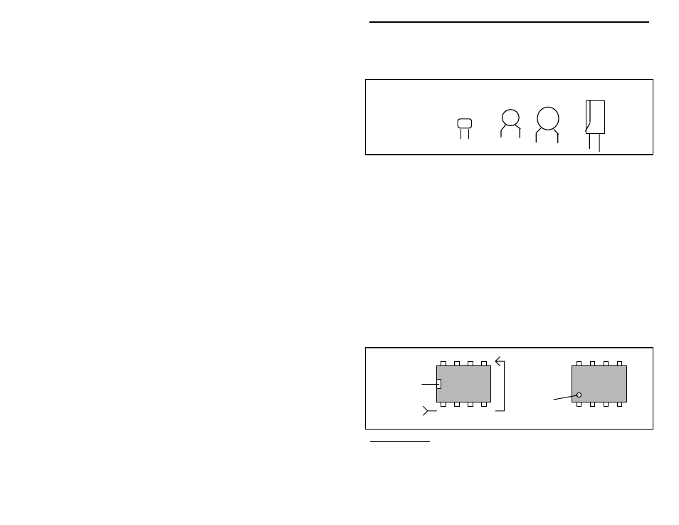
Integrated Circuits: Proper IC positioning is indicated by a dot or square
marking located on one end of the device. A corresponding mark will be silk-
screened on the PC board and printed on the kit's parts-placement diagram. To
identify specific IC pin numbers for testing purposes, see the diagram below.
Pin numbers always begin at "1" at the keyed end of the case and progress along
the device, as shown:
1 2 3 4
8 7 6 5
Installation
Key
Key
Installation
Pin Numbers
PARTS LIST
Your kit should contain all of the parts listed below. Please identify and
inventory each item on the checklist before you start building. If any parts are
missing or damaged, refer to the manual's warranty section for replacement