Vectronics VEC-1320K User Manual
Page 25
VEC-1320K/1330K/1340K/1380K Owner's
Manual
23
! ! 2. Install a DPDT switch at SW2 and solder in place.
! ! 3. Locate the 100 pF trimcap. Install at C1 and solder.
! ! 4. Locate the RCA pc mounted jack. Install at J2 and solder all tabs in
place.
! ! 5. Locate the 2.1 mm DC power jack. Install at J1, seating the case flat
against the surface of the pc board. Twist each solder tab slightly to
secure the jack place, and solder all three.
! ! 6. Locate a length of insulated hook-up and prepare two (2) 2" lengths.
! ! 7. Install one wire at the "Key" pad and solder.
! ! 8. Install one wire at the "Speaker" pad and solder.
Find the plastic-encased variable capacitor. This is the transmitter's VXO tuning
control (C16).
Locate the small strip of double-sided tape. Also, find the two heavy-gauge
leads removed from the 1N4007 diode. These items will be used to secure C16
in place.
! ! 9. Using scissors or a hobby knife, cut a ½" by ¾" square of double-sided
tape. Install this within the box printed at C16 on the pc board (see
diagram).
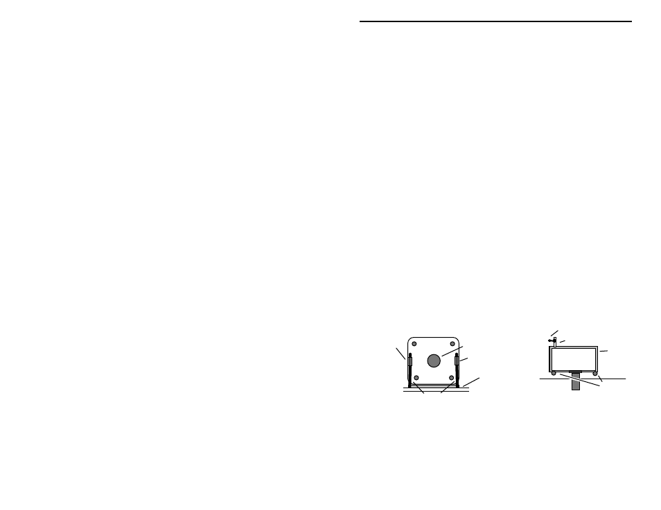
To orient the variable capacitor for installation, use the following diagram.
There should be a ground tab to the left and right of the shaft. At the rear of the
cap, a solder tab will protrude from the case at lower left. When the cap is
positioned as shown, press it down onto the tape to secure it in place.
VXO Capacitor
Heavy Leads
Shaft
Double-sided Tape
VXO
Capacitor
C16 connection
Tab
Tape
Ground Tab
Ground Tab
Ground
Tabs
Front View
Top View
! ! 10. Install two (2) heavy leads (from the 1N4007 diode) from the ground
tabs to the pads provided on the front of the pc board. Solder each
lead at both ends. The combined holding action of the two-sided tape
and the ground leads should anchor the cap firmly in place. Rotate the
cap through its range--the capacitor should not shift position.