Vectronics VEC-820KC User Manual
Page 6
VEC-820KC Assembly Manual
Super CW Audio Filter
6
! ! 5. Connect the 2¼" wire between the short lug on the ¼" phone jack and
the solder lug located at Point C. Solder both ends of the wire in
place.
! ! 6. Wire the filter ground by: a.) Remove the BLACK battery wire from
the point labeled GND on the PC board. b.) Insert one end of the an
insulated wire (3 3/4" long) into the hole at the point labeled GND on
the PC board, then solder in place. c.) Connect the other end of the
insulated wire, at point GND, to the angled solder lug. d.) Connect the
BLACK battery snap wire to the angled solder lug. e.) Solder all
wires connected to the angled solder lug.
! ! 7. Locate C11 which is already connected to SW1. Connect the negative
end of C11 to the long lug on the ¼" phone jack. Solder in place.
Important Note: There are two vertical rows of solder contacts on the backside
of SW2. You can use either vertical row, but only use one row.
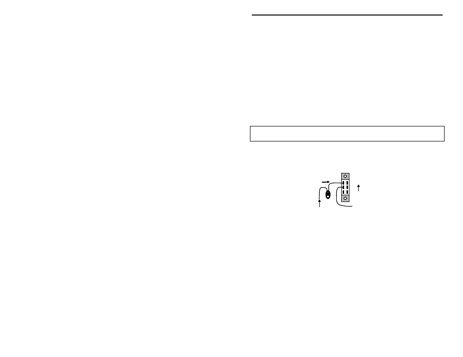
! ! 8. Locate the insulated wire on the circuit board at the point labeled
VCC. Connect this wire to the middle lug on SW2 as shown in the
figure below:
Red Lead (+)
Black Lead (-)
Insulated Wire (VCC)
SW2
ON
! ! 9. Connect the RED battery snap wire to the top lug on SW2 as shown in
the above figure. Solder this wire and the one from step #8.
! ! 10. Locate the four (4) rubber feet. Remove each of them from the
adhesive strip one at a time and stick at each corner on the bottom of
the chassis. These are to keep the VEC-820K from sliding around on
the desktop.
! ! 11. Locate the piece of double-sided tape . This is to be used for holding
the 9-volt battery in place. Locate a place on the underside of the top
cover where the battery will not interfere with any components. Peel
off the backing of the tape and stick it to the chosen location.