Vectronics VC-300D User Manual
Page 6
VC-300D Digital Bargraph Antenna Tuner
Owner's Manual
6
TUNING
1. Select the band and frequency of desired operation.
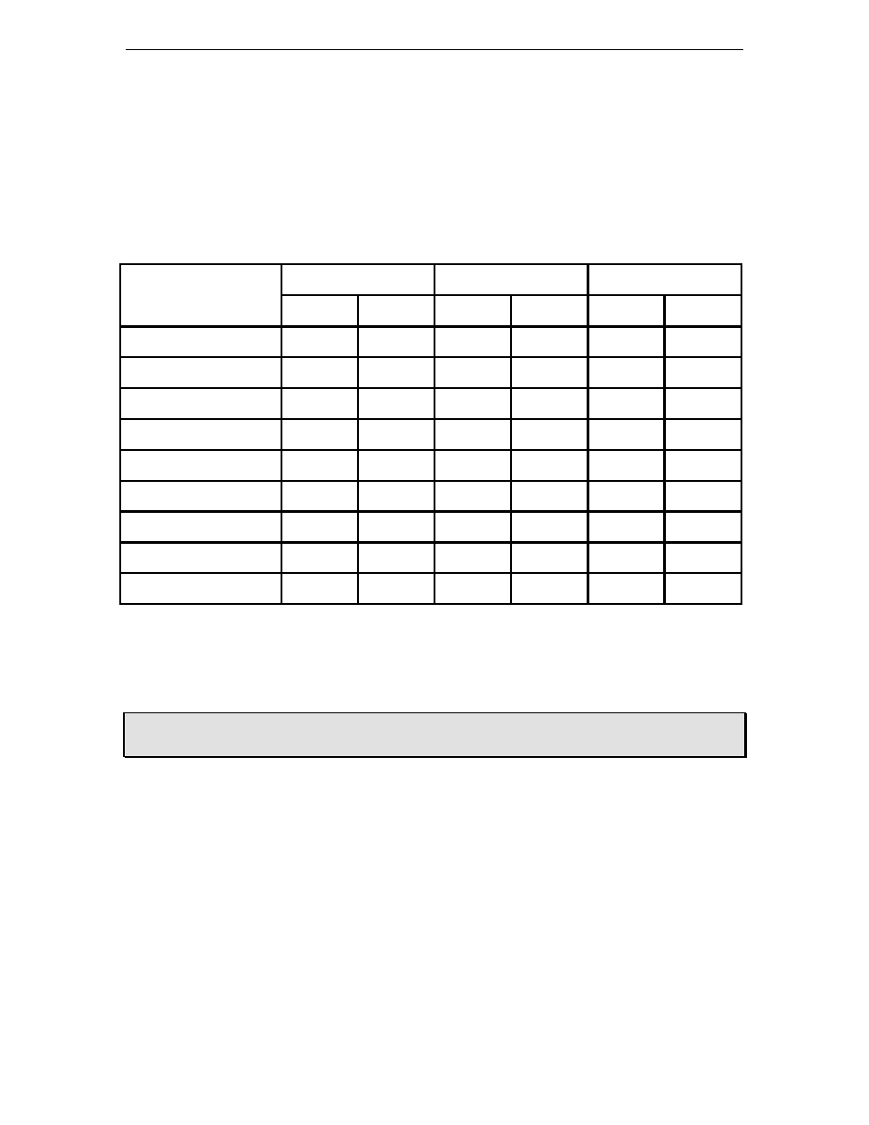
2. Set TRANSMITTER, ANTENNA, and INDUCTOR controls to the suggested
settings before applying transmitter power. Actual settings may vary from antenna to
antenna.
BAND/
TRANSMITTER
ANTENNA
INDUCTANCE
FREQUENCY
Sug. Actual Sug. Actual Sug. Actual
160 M / 1.8 MHz
5
5
L
75 M / 3.75 MHz
3
3
H
40 M / 7.15 MHz
3
3
E
30 M / 10.125 MHz
3
3
C
20 M / 14.175 MHz
2
2
B
17 M / 10.118 MHz
3
3
A
15 M / 21.225 MHz
4
4
A
12 M / 24.940 MHz
5
5
A
10 M / 28.850 MHz
4
4
A
3. Set up your transmitter to a low power output. If your transmitter has a TUNE
position, select that position.
4. If you use a linear amplifier, set it to STANDBY. Do not use the linear amplifier
until the VC-300D is tuned.
WARNING: DO NOT EXCEED 150 WATTS ON ANY BAND WHERE THE
SWR ON THE ANTENNA IS GREATER THAN 4 TO 1.
5. Set RANGE switch to 30W (button IN).
6. Set OUTPUT SELECTOR switch to the proper selection on the TUNED side of the
switch. Selecting any of the DIRECT positions bypasses the tuning circuitry all
together.
7. Rotate the TRANSMITTER, ANTENNA, and INDUCTOR controls for maximum
noise or signal as heard on your receiver.
8. Key your transmitter and adjust the power level for a reading of 10 watts on the
FORWARD scale. Adjust the TRANSMITTER, ANTENNA, and INDUCTOR
controls for a minimum REFLECTED reading while maintaining a FORWARD
reading of 10 watts using your transmitter power control.