Vectronics VC-300D User Manual
Page 9
VC-300D Digital Bargraph Antenna Tuner
Owner's Manual
9
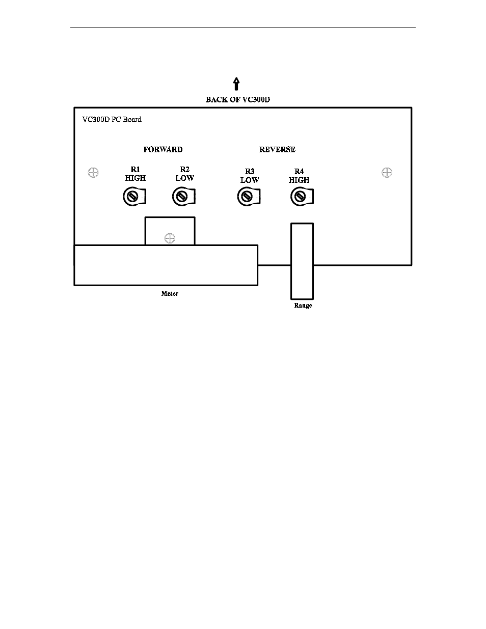
METER CALIBRATION
METER CALIBRATION PEOCEDURE
••••
Connect transceiver to TRANSMITTER IN connector.
••••
Connect external 50
Ω
load to COAX 2 connector.
••••
Set the OUTPUT SELECT switch to the COAX 2 DIRECT position.
••••
Set the RANGE button to 300 W and the PEAK/AVG button to AVG.
••••
Apply 100W of RF at 14.0 MHz.
••••
Adjust R1 (see Figure 1) so that 100W of FORWARD power is read on the
meter.
••••
Reduce the RF power to 10W and set the RANGE to 30W
••••
Adjust R2 so that 10W of FORWARD power is read on the meter.
••••
Reverse the transceiver and load connectors on the rear panel
••••
Set the RANGE to 300W.
••••
Apply 10W of RF power and adjust R4 to read 10W of REFLECTED power.
••••
Set the RANGE to 30W.
••••
Apply 2W of RF power and adjust R3 to read 2W of REFLECTED power.