Apantac HDMI 4x8 User Manual
Startup and installation, Operation
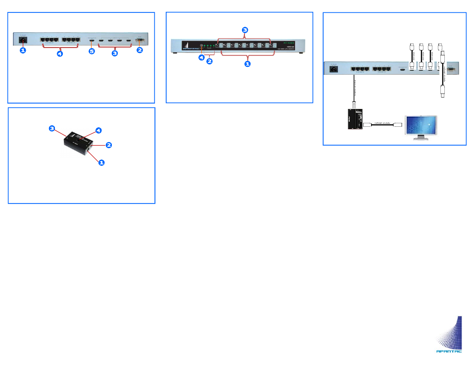
HDMI 4x8 Rear Panel Description
1. Power Port: AC 120/240 V
2. Control Port: RS232
3. HDMI
Inputs
4. Extended
RJ34
Outputs
5. EDID Learning Port
HDMI-1-R (Long Distance Receiver)
1. RJ45 Input from HDMI 4x8
2. Power Port: 5V 1A DC
3. HDMI Output to Monitor
4. Equalization
Adjustment
1. Startup and Installation
The CAT5e/6 cable frequency response
(1) Any CAT5/5e/6 cables will work but the maximum
distance can easily vary depending on the cable
performance. We have tested and recommend the
following cables:
Belden 7989R, Belden 7988R, Belden 1700A
Cable master (Hyper-Data 200 CM 24AWG
4PR 75C (UL) E151955
(2) Keep in mind that cables that would seem to work
properly for Ethernet connectivity applications may
behave poorly in carrying digital video signals.
Skew
The skew represents the difference in propagatin delay
between the fastest and the slowest set of pairs. A lower
skew value will mean a longer video transmitting distance.
Excessive skew may result in one of the RGB components
being offset by one pixel on the display
RJ45 Terminations: Must be done according to
the EIA 568B specifications
Installing the HDMI 4x8
Installing the HDMI 4x8
(1) For first time installation,
Power off all devices
The HDMI 4x8 should be situated in a well
ventilated space
The HDMI 4x8 is rack mountable. To install
the rack ears, simply remove the side screws
on the chassis and attached the rack ears
with the same screws
Connect HDMI source device to HDMI –4x8
Installing the HDMI-1-R
(1) Place the HDMI-1-R receiver next to the monitor
The HDMI-1-R receiver can be up to 115 ft /
35 m away from the HDMI 4x8 switch
(2) Connect the HDMI cable from the HDMI-1-R to
the Monitor
(3) Connect the CATx cable to both the HDMI 4x8 and
HDMI-1-R
(4) Turn on all the source devices
(5) Turn on all the monitors
Equalization Adjustment
(1) Turn the Equalization knob counter clockwise the
end, this will put the equalizers in the “Auto” posi-
tion.
(2) Start from the Auto position, then slowly turn
clockwise until the image is optimized.
2. Operation
(1) Front Panel
A. Push the buttons in the front panel will switch the
HDMI inputs. Green LED on stands for the Source is
connected.
B. The Numerical LEDS shows the destination where
are sources are switched
(2) Remote RS232 Control
A. Port
description
Baud rate = 1200, the baud rate is not con-
figurable
Data bits = 8, parity = none, stop bit = 1,
flow control = none
B.
Protocol
ZS (Destination 1-8, 0 = All) (Source 1-4)
Examples:
ZS14 = Switch source 4 to destination 1
ZS32 = Switch source 2 to destination 3
ZS04 = Switch source 4 to all destinations
1. Output Status LEDs (A, B, C, D, E, F, G, H)
2. Input Status LEDs (1, 2, 3, 4)
3. Selection
Buttons
4. Remote
Port
HDMI 4x8 Front Panel Description
Connection Diagram
HDMI Sources
Apantac LLC
7556 SW Bridgeport Road
Portland, OR 97224
T: +1
(503)
968-3000
F: +1 (503) 389 7921
E: [email protected]
MT Hood HDMI-4x8 012011
Max HDMI cable distance = 15 feet
Max CATx cable distance = 115feet