Apantac KVM-8 User Manual
Startup and installation, Operation
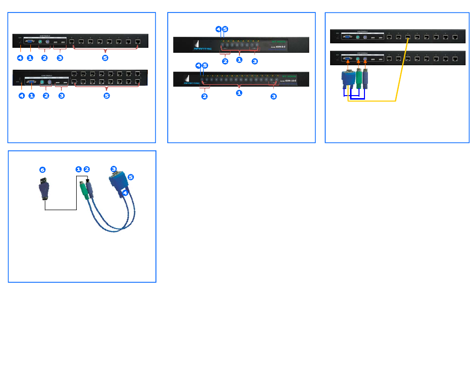
KVM-8/16-E Rear Panel Description
1. Control Console VGA Port
2. Control Console PS2 Keyboard/Mouse Port
3. Control Console USB Keyboard/Mouse Port
4. Power Port: DC 9V
5. RJ45 Port to Connect to PC
UI-200E Universal Interface/Extender
1. PS2 Mouse Connection to PC
2. PS2 Keyboard Connection to PC
3. VGA Connection to PC
4. RJ45 Connection between PC and KVM Switch
5. System Status Indicator
6. PS2 to USB Converter
1. Startup and Installation
Installing Universal Interface/Extender
(1) Computer with PS2 Keyboard and Mouse
Connect the UI-200E VGA, PS2 Keyboard and
mouse port to the computer.
(2) Computer with USB Keyboard and Mouse
Connect the PS2 to USB converter to the keyboard
PS2 connector, then connect the
the USB end of the PS2/USB converter to the com-
puter’s USB port. It is not necessary to connect the UI
-200E’s PS2 mouse connector to anything. Finally,
connect the VGA port of the UI-200E to the computer’s
VGA port
(3) Functional Test
Turn on the computer, the UI-200E will receive the
power from the PS2 or USB port, the yellow LED on
the RJ45 port will be on.
Installing the KVM Switch
(1) For first time installation,
•
Turn off the computer
•
Connect the monitor, keyboard and mouse to their
perspective port on the control console. Keyboard
and mouse can be connected to either the USB or
PS2 port.
•
Connect the power to the KVM Switch
•
Connect each computer’s UI-200E to the KVM
switch with CAT5/E/6 cable
•
Turn on all the computers
(2) When the KVM powers up the first time, the LEDs on
the front panel will flash once to show that everything
has been properly connected
(3) If an error occurs during the installation, press the two
buttons on the front panel marked “ Reset” simulta-
neously. The connection will reset.
(4) KVM switch can be installed in a 19” rack with the rack
ears supplied.
2. Operation
(1) Front Panel
A. Push the buttons in the front panel will switch the
computer inputs. Green LED on stands for the com-
puter is connected. Orange LED on stands for the
computer is online.
B. Press two buttons on the left together will enable
Auto Scan.
C. If error occurs while hot swapping the keyboard and
mouse, press the 2 buttons on the right together,
will Reset the connection.
(2) Using Hot Keys
A. Press Hot Key, “Scroll Lock”, “Scroll Lock” + buttons
(1 - 8, A - H), to switch the computers inputs on the
KVM switch. After pressing the Hot Key, OSD will
appear on the screen to represent the Hot Keys
B. If there are two switches cascaded together, the
user needs to input a 2 digit value. The left digit will
represent the port on the primary switch (where the
cascading input is located, the right digit will repre-
sent the port on the secondary switch. For example:
Value “63” selects the input port 3 on the secondary
switch and the cascading input to the primary switch
is port 6. (See figure on the next page)
C. Press “Scroll Lock” twice, then “F4”, to enable Auto
Scan. Auto Scan will start from input 1. Use the “-
>“ key to adjust Auto Scan time interval. Auto Scan
time interval can be set from 1—255 seconds. Press
“Scroll Lock” twice, then <ESC> key to stop Auto
Scan
1. Selection Buttons
2. Scan — Push both buttons to start Auto Scan
3. Reset — Push both buttons to reset connection
4. Green LED - Connection Status
5. Orange LED - Online Status
KVM-8/16-E Front Panel Description
Up to 2 levels of Cascade for Expansion
1. Connect UI-200E to the secondary KVM
2. Connect the CATx between the UI-200E to any
RJ45 port on the primary KVM
Cascading Multiple Switches Together
CATx Cable
Primary KVM
Secondary KVM